RM0401 Rev 3 451/771
RM0401 Low-power timer (LPTIM)
472
18.4 LPTIM functional description
18.4.1 LPTIM block diagram
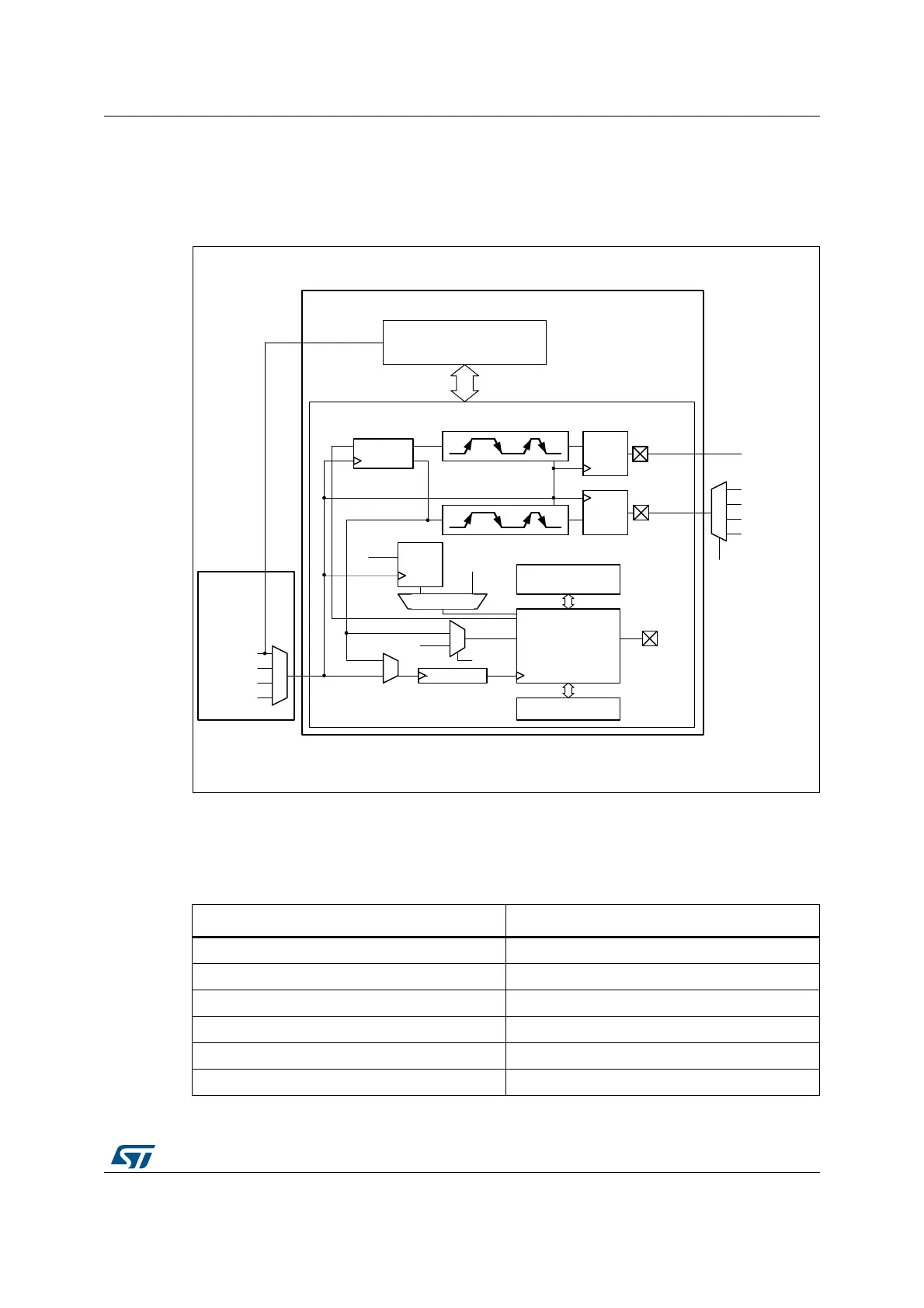
Figure 166. Low-power timer block diagram
18.4.2 LPTIM trigger mapping
The LPTIM external trigger connections are detailed hereafter:
06Y9
5&&
/37,0
$3%B,7)
.HUQHO
VZ
WULJJHU
XSWRH[W
WULJJHU
&/.08;
+6,
/6,
/6(
$3%FORFN
ELWFRPSDUH
ELWFRXQWHU
ELW$55
2XW
3UHVFDOHU
0X[WULJJHU
*OLWFK
ILOWHU
*OLWFK
ILOWHU
,QSXW
(QFRGHU
*OLWFK
ILOWHU
,QSXW
8SGRZQ
&2817
02'(
$)SDGLQSXW
3$SDG
3%SDG
7,0'$&WULJJHU
/37,0B25
$)SDGLQSXW
Table 72. LPTIM1 external trigger connection
TRIGSEL External trigger
lptim_ext_trig0 PB6 or PC3 input on AF1
lptim_ext_trig1 RTC alarm A output signal
lptim_ext_trig2 RTC alarm B output signal
lptim_ext_trig3 RTC tamper output signal
lptim_ext_trig4 TIM1 trigger output (0) output signal
lptim_ext_trig5 TIM5 trigger output (3) output signal

 Loading...


