True random number generator (RNG) RM0401
258/771 RM0401 Rev 3
13.3 RNG functional description
13.3.1 RNG block diagram
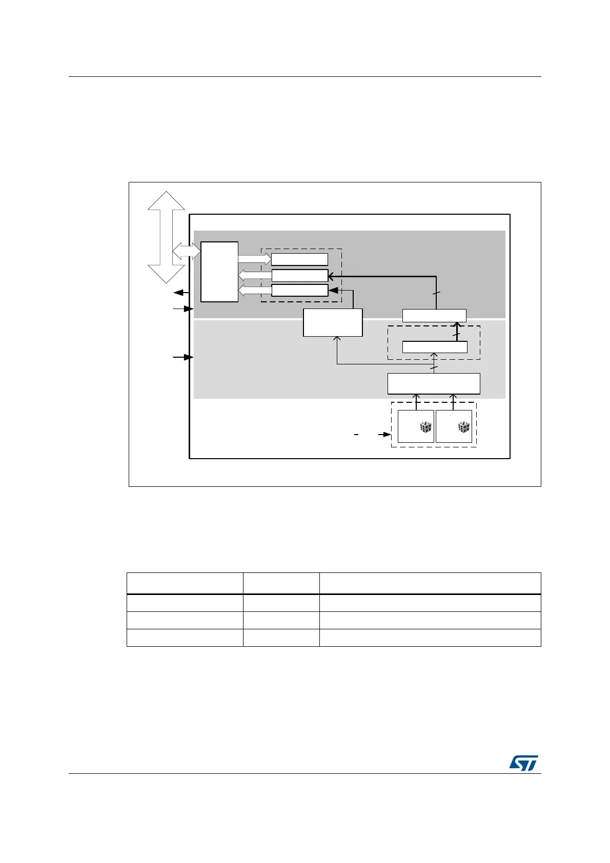
Figure 47 shows the RNG block diagram.
Figure 47. RNG block diagram
13.3.2 RNG internal signals
Table 54 describes a list of useful-to-know internal signals available at the RNG level, not at
the STM32 product level (on pads).
06Y9
751*Y
51*B65
$+%
LQWHUIDFH
VWDWXV
51*B&5
$QDORJ
QRLVH
VRXUFH
%DQNHG5HJLVWHUV
6DPSOLQJ
1RUPDOL]DWLRQ[
$QDORJQRLVHVRXUFH
ELW
$QDORJ
QRLVH
VRXUFH
HQBRVF
ELW$+%%XV
UQJBLW
UQJBKFON
UQJBFON
$+%FORFNGRPDLQ
51*FORFNGRPDLQ
'DWDVKLIWUHJ
ELW
ELW/)65[
3RVWSURFHVVLQJORJLF
ELW
)DXOWGHWHFWLRQ
&ORFNFKHFNHU
$ODUPV
51*B'5
GDWD
FRQWURO
Table 54. RNG internal input/output signals
Signal name Signal type Description
rng_it Digital output RNG global interrupt request
rng_hclk - Digital input AHB - clock
rng_clk Digital input RNG dedicated clock, asynchronous to rng_hclk -