Direct memory access controller (DMA) RM0401
166/771 RM0401 Rev 3
controller accesses the peripheral, an Acknowledge signal is sent to the peripheral by the
DMA controller. The peripheral releases its request as soon as it gets the Acknowledge
signal from the DMA controller. Once the request has been deasserted by the peripheral,
the DMA controller releases the Acknowledge signal. If there are more requests, the
peripheral can initiate the next transaction.
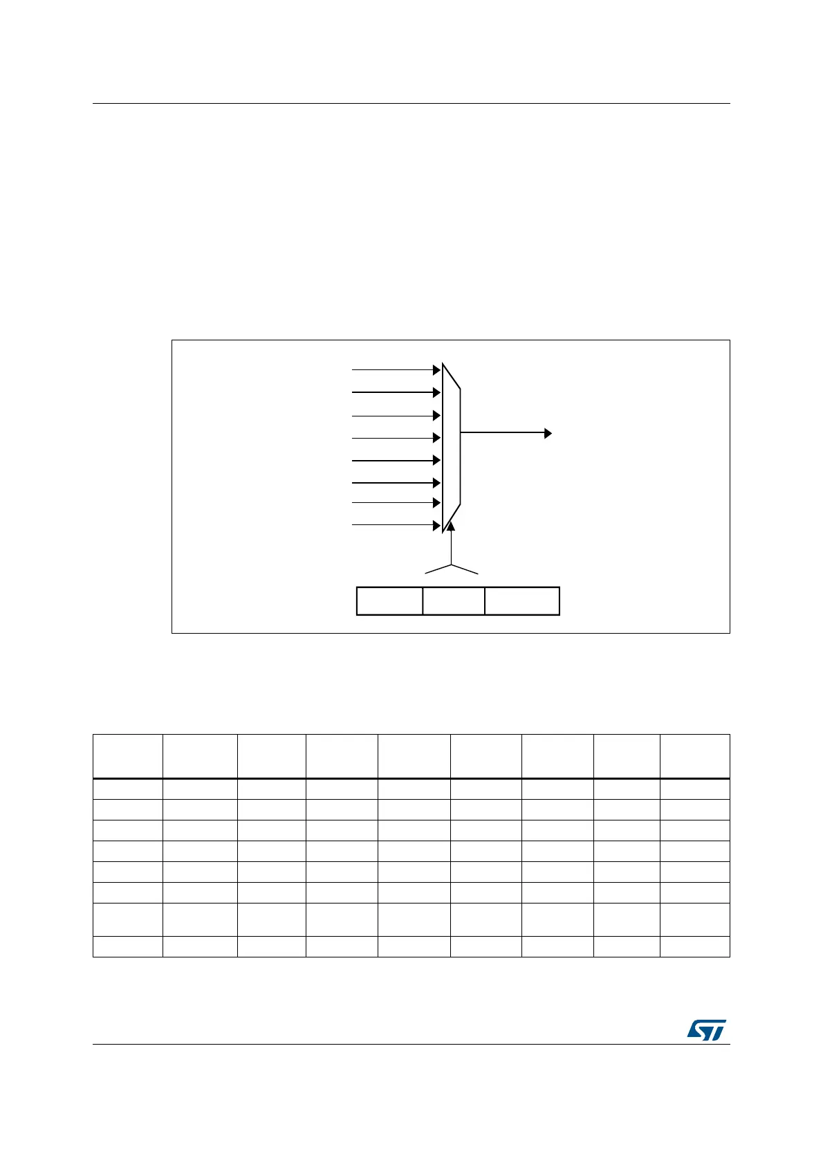
8.3.4 Channel selection
Each stream is associated with a DMA request that can be selected out of 8 possible
channel requests. The selection is controlled by the CHSEL[2:0] bits in the DMA_SxCR
register.
Figure 24. Channel selection
The 8 requests from the peripherals (such as TIM, ADC, SPI, I2C) are independently
connected to each channel and their connection depends on the product implementation.
Table 29 and Table 30 give examples of DMA request mappings.
5(4B675($0[
5(4B675[B&+
&+6(/>@
'0$B6[&5
DLE
5(4B675[B&+
5(4B675[B&+
5(4B675[B&+
5(4B675[B&+
5(4B675[B&+
5(4B675[B&+
5(4B675[B&+
Table 29. DMA1 request mapping
Peripheral
requests
Stream 0 Stream 1 Stream 2 Stream 3 Stream 4 Stream 5 Stream 6 Stream 7
Channel 0 - I2C1_TX - SPI2_RX SPI2_TX - - -
Channel 1 I2C1_RX - - I2C4_RX - I2C1_RX I2C1_TX I2C1_TX
Channel 2 - I2C4_TX - - - - - -
Channel 3 - - - - - - - -
Channel 4 - - - - - USART2_RX USART2_TX I2C4_TX
Channel 5 - - - - - - - -
Channel 6
TIM5_CH3
TIM5_UP
TIM5_CH4
TIM5_TRIG
TIM5_CH1
TIM5_CH4
TIM5_TRIG
TIM5_CH2 - TIM5_UP USART2_RX
Channel 7 I2C4_RX TIM6_UP I2C2_RX I2C2_RX - DAC1 DAC2 I2C2_TX