Serial peripheral interface/ inter-IC sound (SPI/I2S) RM0401
704/771 RM0401 Rev 3
25.6 I
2
S functional description
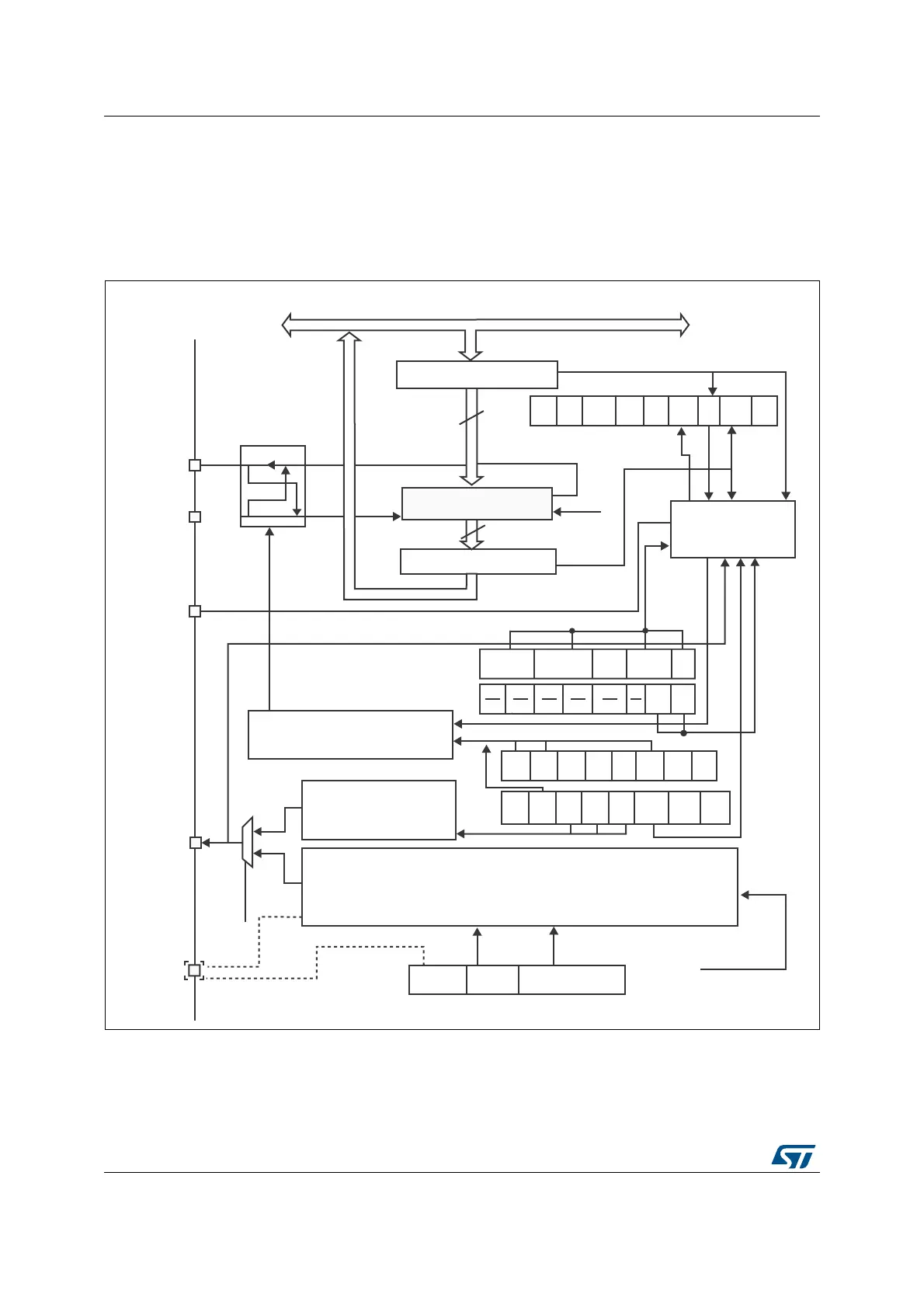
25.6.1 I
2
S general description
The block diagram of the I
2
S is shown in Figure 252.
Figure 252. I
2
S block diagram
1. MCK is mapped on the MISO pin.
The SPI can function as an audio I
2
S interface when the I
2
S capability is enabled (by setting
the I2SMOD bit in the SPIx_I2SCFGR register). This interface mainly uses the same pins,
flags and interrupts as the SPI.
7[EXIIHU
6KLIWUHJLVWHU
ELW
&RPPXQLFDWLRQ
5[EXIIHU
ELW
026,6'
0DVWHUFRQWUROORJLF
0,62
63,
EDXGUDWHJHQHUDWRU
,602'
/6%ILUVW
/6%
)LUVW
63( %5 %5 %5 0675
&32/ &3+$
%LGL
PRGH
%LGL
2(
&5&
(1
&5&
1H[W
'))
5[
RQO\
660
66,
$GGUHVVDQGGDWDEXV
FRQWURO
166:6
%6< 295 02')
&5&
(55
&+
6,'(
7[( 5[1(
,
6FORFNJHQHUDWRU
0&.
,6B
&.
,6
02'
,6(
&+
'$7/(1
/(1
&.
32/
,6&)*
,667'
0&.2( 2'' ,6',9>@
>@
>@
>@
8'5
,6[&/.
069
)5(
&.