Serial peripheral interface/ inter-IC sound (SPI/I2S) RM0401
698/771 RM0401 Rev 3
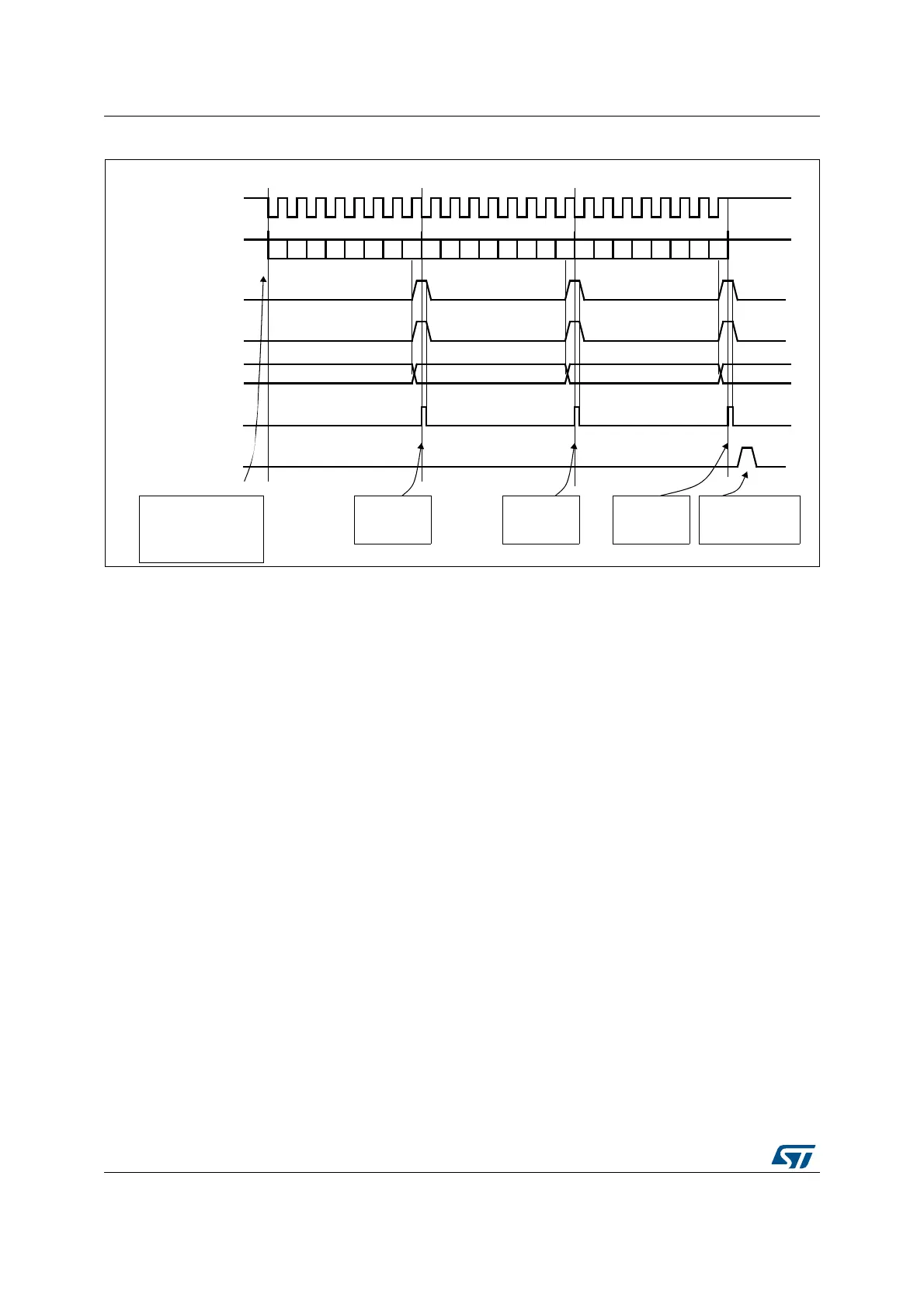
Figure 250. Reception using DMA
25.3.12 SPI status flags
Three status flags are provided for the application to completely monitor the state of the SPI
bus.
Tx buffer empty flag (TXE)
When it is set, the TXE flag indicates that the Tx buffer is empty and that the next data to be
transmitted can be loaded into the buffer. The TXE flag is cleared by writing to the SPI_DR
register.
Rx buffer not empty (RXNE)
When set, the RXNE flag indicates that there are valid received data in the Rx buffer. It is
cleared by reading from the SPI_DR register.
Busy flag (BSY)
The BSY flag is set and cleared by hardware (writing to this flag has no effect).
When BSY is set, it indicates that a data transfer is in progress on the SPI (the SPI bus is
busy). There is one exception in master bidirectional receive mode (MSTR=1 and BDM=1
and BDOE=0) where the BSY flag is kept low during reception.
The BSY flag can be used in certain modes to detect the end of a transfer, thus preventing
corruption of the last transfer when the SPI peripheral clock is disabled before entering a
low-power mode or an NSS pulse end is handled by software.
The BSY flag is also useful for preventing write collisions in a multimaster system.
0,62026,LQ
'$7$ [$
VRIWZDUHFRQILJXUHVWKH
'0$63,5[FKDQQHO
WRUHFHLYHGDWDLWHPV
DQGHQDEOHVWKH63,
6&.
'$7$ [$
'$7$ [$
([DPSOHZLWK&32/ &3+$
5;1(IODJ
5[EXIIHU
VHWE\KDUGZDUH
UHDGIURP63,B'5
[$
[$ [$
'0$UHTXHVW
'0$UHDGV
'$7$IURP
63,B'5
IODJ'0$7&,)
VHWE\KDUGZDUH
FOHDU
E\VRIWZDUH
'0$UHDGIURP63,B'5
7KH'0$WUDQVIHULV
FRPSOHWH7&,) LQ
'0$B,65
'0$UHDGV
'$7$IURP
63,B'5
'0$UHDGV
'$7$IURP
63,B'5
'0$WUDQVIHUFRPSOHWH
E E E E E E E E E E E E E E E E E E E E E E E E
FOHDUE\'0$UHDG
DL