Universal synchronous receiver transmitter (USART) /universal asynchronous receiver transmit-
666/771 RM0401 Rev 3
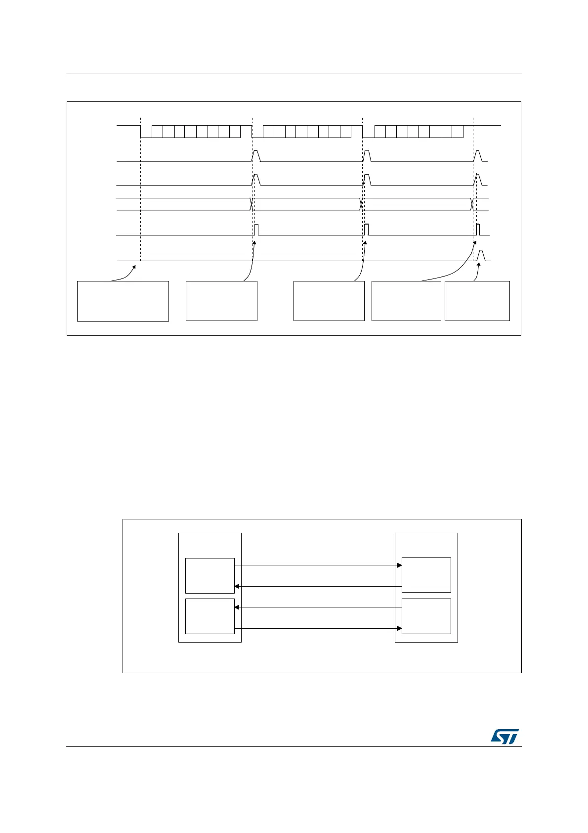
Figure 234. Reception using DMA
Error flagging and interrupt generation in multibuffer communication
In case of multibuffer communication if any error occurs during the transaction the error flag
will be asserted after the current byte. An interrupt will be generated if the interrupt enable
flag is set. For framing error, overrun error and noise flag that are asserted with RXNE in
case of single byte reception, there will be separate error flag interrupt enable bit (EIE bit in
the USART_CR3 register), which if set will issue an interrupt after the current byte with
either of these errors.
24.4.14 Hardware flow control
It is possible to control the serial data flow between 2 devices by using the nCTS input and
the nRTS output. The Figure 235 shows how to connect 2 devices in this mode:
Figure 235. Hardware flow control between 2 USARTs
RTS and CTS flow control can be enabled independently by writing respectively RTSE and
CTSE bits to 1 (in the USART_CR3 register).
7;OLQH
)UDPH
)
)
6HWE\KDUGZDUH
FOHDUHGE\'0$UHDG
)
DLE
)UDPH
)UDPH
5;1(IODJ
86$57B7'5
'0$UHTXHVW
'0$UHDGV
86$57B7'5
'0$7&,)IODJ
WUDQVIHUFRPSOHWH
6RIWZDUHFRQILJXUHVWKH
'0$WRUHFHLYHGDWD
EORFNVDQGHQDEOHV
WKH86$57
'0$UHDGV)
IURP86$57B7'5
7KH'0$WUDQVIHU
LVFRPSOHWH
7&,) LQ
'0$B,65
6HWE\KDUGZDUH
&OHDUHG
E\
VRIWZDUH
'0$UHDGV)
IURP86$57B7'5
'0$UHDGV)
IURP86$57B7'5
06Y9
7;FLUFXLW
86$57
7;
5;FLUFXLW
5;FLUFXLW
86$57
7;FLUFXLW
7;
Q&76
Q&76
Q576
5;
Q576
5;