RM0401 Rev 3 521/771
RM0401 Real-time clock (RTC)
523
Note: This register can be written only when ALRBIE is reset in RTC_CR register, or in
initialization mode.
This register is write protected.The write access procedure is described in RTC register
write protection
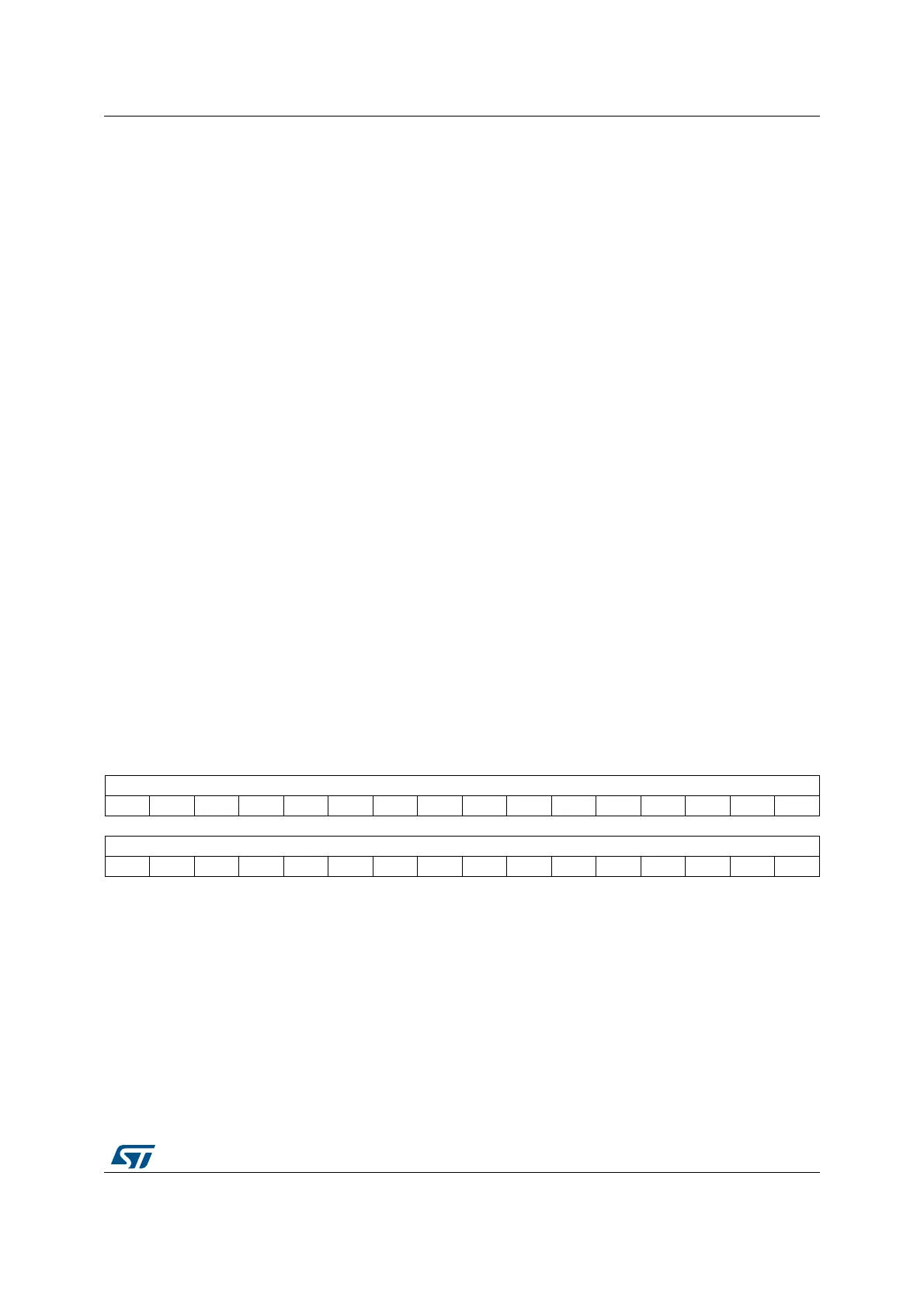
21.6.20 RTC backup registers (RTC_BKPxR)
Address offset: 0x50 to 0x9C
Backup domain reset value: 0x0000 0000
System reset: not affected
Bits 31:28 Reserved, must be kept at reset value
Bits 27:24 MASKSS[3:0]: Mask the most-significant bits starting at this bit
0x0: No comparison on sub seconds for Alarm B. The alarm is set when the seconds unit is
incremented (assuming that the rest of the fields match).
0x1: SS[14:1] are don’t care in Alarm B comparison. Only SS[0] is compared.
0x2: SS[14:2] are don’t care in Alarm B comparison. Only SS[1:0] are compared.
0x3: SS[14:3] are don’t care in Alarm B comparison. Only SS[2:0] are compared.
...
0xC: SS[14:12] are don’t care in Alarm B comparison. SS[11:0] are compared.
0xD: SS[14:13] are don’t care in Alarm B comparison. SS[12:0] are compared.
0xE: SS[14] is don’t care in Alarm B comparison. SS[13:0] are compared.
0xF: All 15 SS bits are compared and must match to activate alarm.
The overflow bits of the synchronous counter (bits 15) is never compared. This bit can be
different from 0 only after a shift operation.
Bits 23:15 Reserved, must be kept at reset value
Bits 14:0 SS[14:0]: Sub seconds value
This value is compared with the contents of the synchronous prescaler’s counter to
determine if Alarm B is to be activated. Only bits 0 up to MASKSS-1 are compared.
31 30 29 28 27 26 25 24 23 22 21 20 19 18 17 16
BKP[31:16]
rw rw rw rw rw rw rw rw rw rw rw rw rw rw rw rw
1514131211109876543210
BKP[15:0]
rw rw rw rw rw rw rw rw rw rw rw rw rw w rw rw
Bits 31:0 BKP[31:0]
The application can write or read data to and from these registers.
They are powered-on by V
BAT
when V
DD
is switched off, so that they are not reset by
System reset, and their contents remain valid when the device operates in low-power mode.
This register is reset on a tamper detection event, as long as TAMPxF=1.