Power controller (PWR) RM0401
72/771 RM0401 Rev 3
regulator can be put either in main regulator mode (MR) or in low-power mode (LPR).
The programmed voltage scale remains the same during Stop mode:
Voltage scale 3 is automatically selected when the microcontroller enters Stop
mode (see Section 4.4.1: PWR power control register (PWR_CR)).
• In Standby mode, the regulator is powered down. The content of the registers and
SRAM are lost except for the Standby circuitry and the backup domain.
Note: For more details, refer to the voltage regulator section in the datasheet.
4.2 Power supply supervisor
4.2.1 Power-on reset (POR)/power-down reset (PDR)
The device has an integrated POR/PDR circuitry that allows proper operation starting
from 1.8 V.
To use the device below 1.8 V, the internal power supervisor must be switched off using the
PDR_ON pin (please refer to section Power supply supervisor of the datasheet). The device
remains in Reset mode when V
DD
/V
DDA
is below a specified threshold, V
POR/PDR
, without
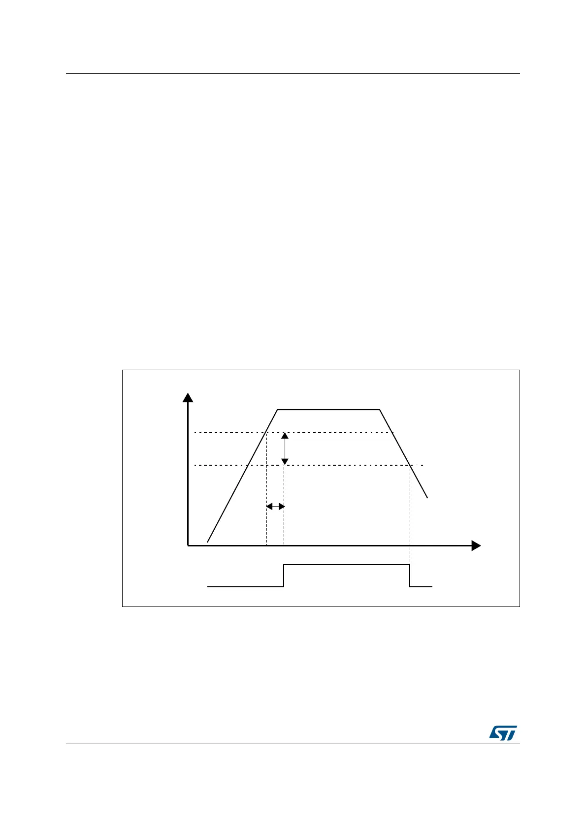
the need for an external reset circuit. For more details concerning the power on/power-down
reset threshold, refer to the electrical characteristics of the datasheet.
Figure 8. Power-on reset/power-down reset waveform
6$$6$$!
M6
HYSTERESIS
0$2
0$2
-36
2ESET
4EMPORIZATION
T2344%-0/