Power controller (PWR) RM0401
74/771 RM0401 Rev 3
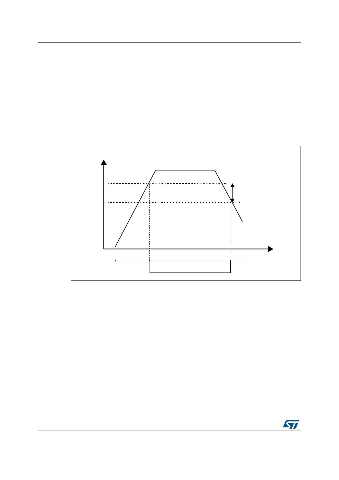
4.2.3 Programmable voltage detector (PVD)
You can use the PVD to monitor the V
DD
power supply by comparing it to a threshold
selected by the PLS[2:0] bits in the
PWR power control register (PWR_CR)
The PVD is enabled by setting the PVDE bit.
A PVDO flag is available, in the PWR power control/status register (PWR_CSR), to indicate
if V
DD
is higher or lower than the PVD threshold. This event is internally connected to the
EXTI line16 and can generate an interrupt if enabled through the EXTI registers. The PVD
output interrupt can be generated when V
DD
drops below the PVD threshold and/or when
V
DD
rises above the PVD threshold depending on EXTI line16 rising/falling edge
configuration. As an example the service routine could perform emergency shutdown tasks.
Figure 10. PVD thresholds
4.3 Low-power modes
By default, the microcontroller is in Run mode after a system or a power-on reset. In Run
mode the CPU is clocked by HCLK and the program code is executed. Several low-power
modes are available to save power when the CPU does not need to be kept running, for
example when waiting for an external event. It is up to the user to select the mode that gives
the best compromise between low-power consumption, short startup time and available
wakeup sources.
The devices feature four low-power modes:
• Sleep mode: Cortex
®
-M4 with FPU core is stopped, peripherals are kept running.
• Stop mode: all clocks are stopped.
• Standby mode: 1.2 V domain is powered off.
• Batch acquisition mode (BAM): the devices are in Sleep mode, the Flash memory is off,
needed peripheral are kept running, data transfer are still possible through DMA.
069
9''
P9
K\VWHUHVLV
39'WKUHVKROG
39'RXWSXW