Low-power timer (LPTIM) RM0401
456/771 RM0401 Rev 3
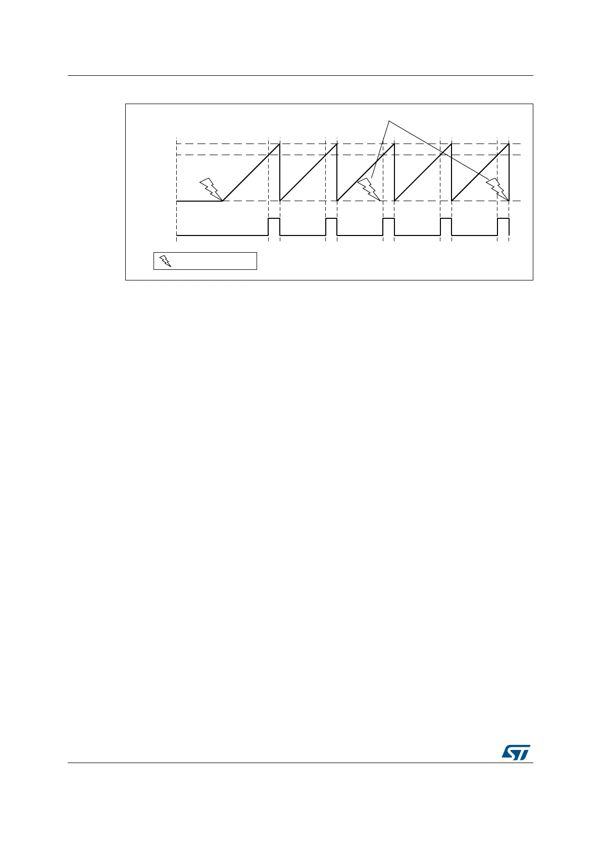
Figure 170. LPTIM output waveform, Continuous counting mode configuration
SNGSTRT and CNTSTRT bits can only be set when the timer is enabled (The ENABLE bit
is set to ‘1’). It is possible to change “on the fly” from One-shot mode to Continuous mode.
If the Continuous mode was previously selected, setting SNGSTRT will switch the LPTIM to
the One-shot mode. The counter (if active) will stop as soon as it reaches ARR.
If the One-shot mode was previously selected, setting CNTSTRT will switch the LPTIM to
the Continuous mode. The counter (if active) will restart as soon as it reaches ARR.
18.4.9 Timeout function
The detection of an active edge on one selected trigger input can be used to reset the
LPTIM counter. This feature is controlled through the TIMOUT bit.
The first trigger event will start the timer, any successive trigger event will reset the counter
and the timer will restart.
A low-power timeout function can be realized. The timeout value corresponds to the
compare value; if no trigger occurs within the expected time frame, the MCU is waked-up by
the compare match event.
18.4.10 Waveform generation
Two 16-bit registers, the LPTIM_ARR (autoreload register) and LPTIM_CMP (compare
register), are used to generate several different waveforms on LPTIM output
The timer can generate the following waveforms:
• The PWM mode: the LPTIM output is set as soon as the counter value in LPTIM_CNT
exceeds the compare value in LPTIM_CMP. The LPTIM output is reset as soon as a
match occurs between the LPTIM_ARR and the LPTIM_CNT registers.
• The One-pulse mode: the output waveform is similar to the one of the PWM mode for
the first pulse, then the output is permanently reset
• The Set-once mode: the output waveform is similar to the One-pulse mode except that
the output is kept to the last signal level (depends on the output configured polarity).
The above described modes require that the LPTIM_ARR register value be strictly greater
than the LPTIM_CMP register value.
06Y9
3:0
&RPSDUH
/37,0B$55
'LVFDUGHGWULJJHUV
([WHUQDOWULJJHUHYHQW