General-purpose I/Os (GPIO) RM0401
144/771 RM0401 Rev 3
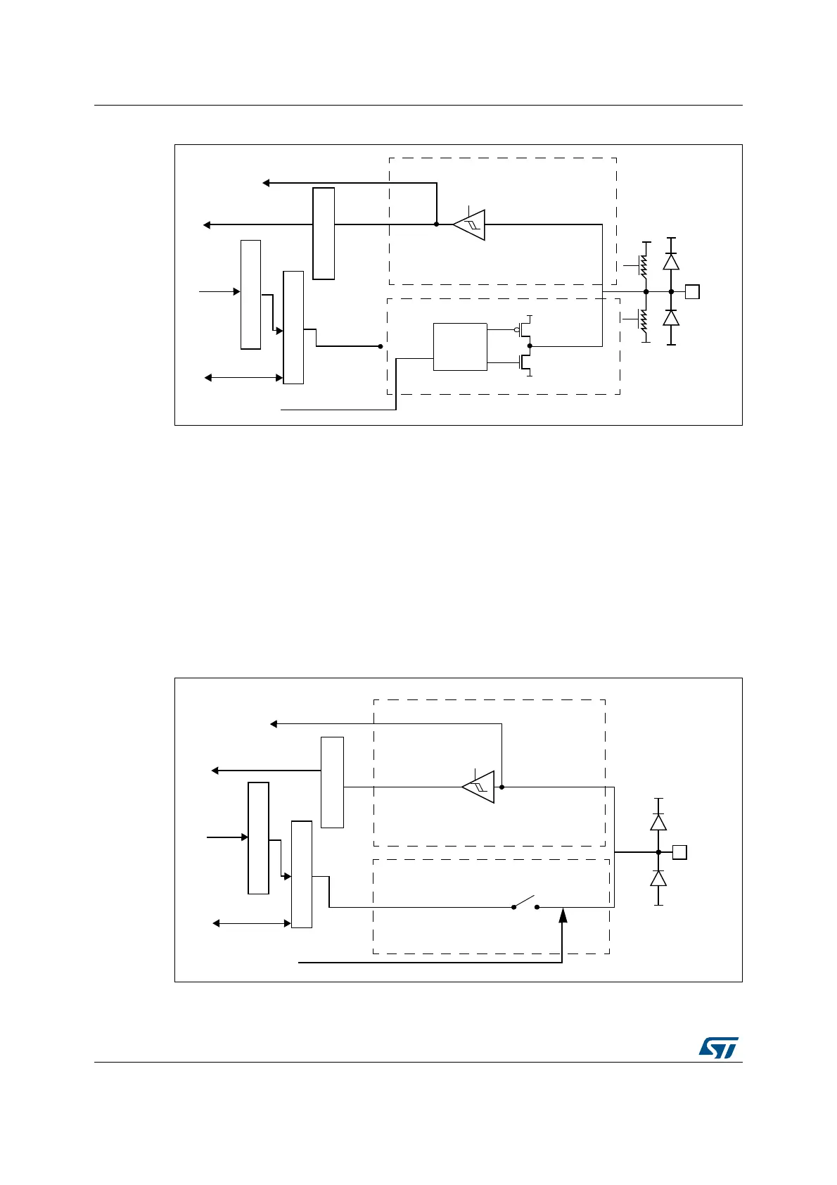
Figure 20. Alternate function configuration
6.3.12 Analog configuration
When the I/O port is programmed as analog configuration:
• The output buffer is disabled
• The Schmitt trigger input is deactivated, providing zero consumption for every analog
value of the I/O pin. The output of the Schmitt trigger is forced to a constant value (0).
• The weak pull-up and pull-down resistors are disabled
• Read access to the input data register gets the value “0”
Note: In the analog configuration, the I/O pins cannot be 5 Volt tolerant.
Figure 21 shows the high-impedance, analog-input configuration of the I/O port bit.
Figure 21. High impedance-analog configuration
!LTERNATEFUNCTIONOUTPUT
!LTERNATEFUNCTIONINPUT
PUSHPULLOR
OPENDRAIN
&ROMONCHIP
PERIPHERAL
4OONCHIP
PERIPHERAL
/UTPUT
CONTROL
6
$$
6
33
44,3CHMITT
TRIGGER
ON
)NPUTDRIVER
/UTPUTDRIVER
0-/3
.-/3
)NPUTDATAREGISTER
/UTPUTDATAREGISTER
2EADWRITE
2EAD
"ITSETRESETREGISTERS
7RITE
ONOFF
ONOFF
6
$$
6
33
6
33
6
$$
PROTECTION
DIODE
PROTECTION
DIODE
0ULL
0ULL
)/PIN
DOWN
UP
AIB
&ROMONCHIP
PERIPHERAL
4OONCHIP
PERIPHERAL
!NALOG
TRIGGER
OFF
)NPUTDRIVER
)NPUTDATAREGISTER
/UTPUTDATAREGISTER
2EADWRITE
2EAD
"ITSETRESETREGISTERS
7RITE
!NALOG
6
33
6
$$
PROTECTION
DIODE
PROTECTION
DIODE
)/PIN
AI