RM0401 Rev 3 605/771
RM0401 Inter-integrated circuit (I
2
C) interface
626
Overrun/underrun error (OVR)
An overrun error can occur in slave mode when clock stretching is disabled and the I
2
C
interface is receiving data. The interface has received a byte (RxNE=1) and the data in DR
has not been read, before the next byte is received by the interface. In this case,
• The last received byte is lost.
• In case of Overrun error, software should clear the RxNE bit and the transmitter should
re-transmit the last received byte.
Underrun error can occur in slave mode when clock stretching is disabled and the I
2
C
interface is transmitting data. The interface has not updated the DR with the next byte
(TxE=1), before the clock comes for the next byte. In this case,
• The same byte in the DR register will be sent again
• The user should make sure that data received on the receiver side during an underrun
error are discarded and that the next bytes are written within the clock low time
specified in the I
2
C bus standard.
For the first byte to be transmitted, the DR must be written after ADDR is cleared and before
the first SCL rising edge. If not possible, the receiver must discard the first data.
23.3.5 Programmable noise filter
In Fm mode, the I
2
C standard requires that spikes are suppressed to a length of 50 ns on
SDA and SCL lines.
An analog noise filter is implemented in the SDA and SCL I/Os. This filter is enabled by
default and can be disabled by setting the ANOFF bit in the I2C_FLTR register.
A digital noise filter can be enabled by configuring the DNF[3:0] bits to a non-zero value.
This suppresses the spikes on SDA and SCL inputs with a length of up to DNF[3:0] *
T
PCLK1
.
Enabling the digital noise filter increases the SDA hold time by (DNF[3:0] +1)* T
PCLK
.
To be compliant with the maximum hold time of the I
2
C-bus specification version 2.1
(Thd:dat), the DNF bits must be programmed using the constraints shown in Table 101, and
assuming that the analog filter is disabled.
Note: DNF[3:0] must only be configured when the I
2
C is disabled (PE = 0). If the analog filter is
also enabled, the digital filter is added to the analog filter.
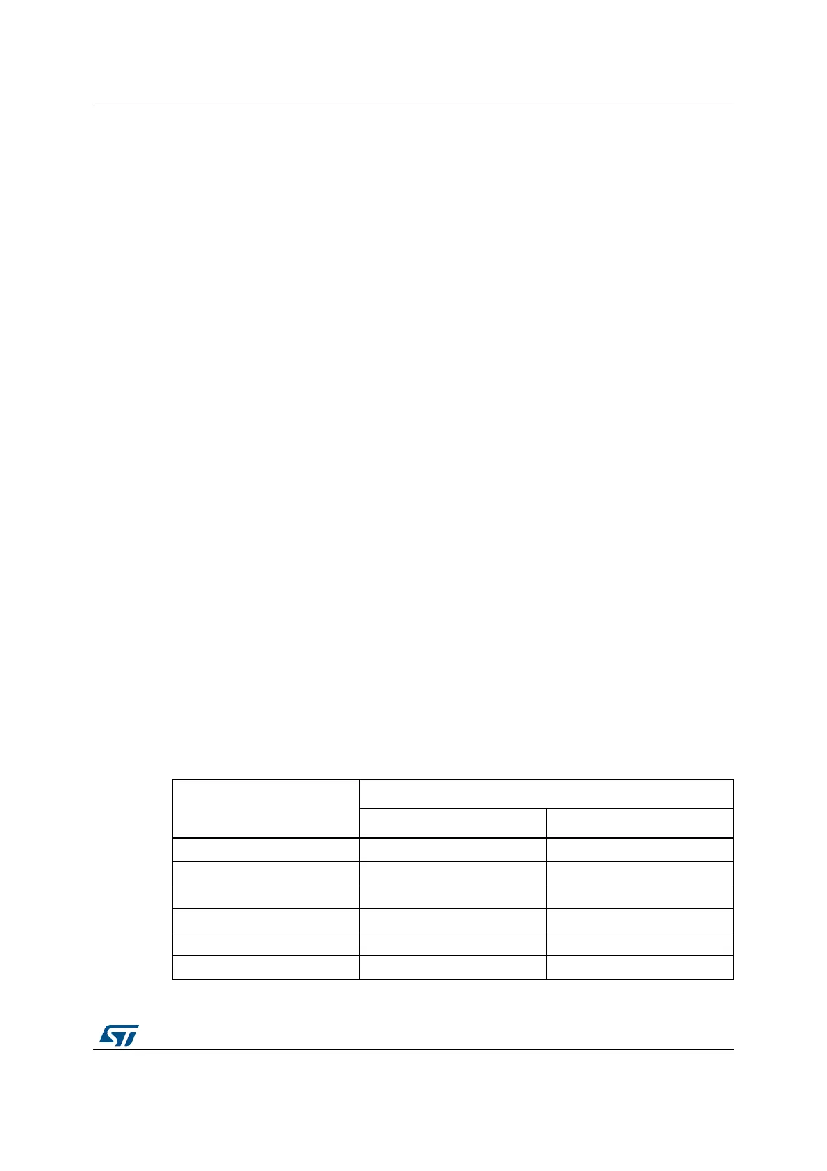
Table 101. Maximum DNF[3:0] value to be compliant with Thd:dat(max)
PCLK1 frequency
Maximum DNF value
Sm mode Fm mode
2 <= F
PCLK1
<= 5 2 0
5 < F
PCLK1
<= 10 12 0
10 < F
PCLK1
<= 20 15 1
20 < F
PCLK1
<= 30 15 7
30 < F
PCLK1
<= 40 15 13
40 < F
PCLK1
<= 50 15 15