RM0401 Rev 3 713/771
RM0401 Serial peripheral interface/ inter-IC sound (SPI/I2S)
731
Note: For both modes (master and slave) and for both synchronizations (short and long), the
number of bits between two consecutive pieces of data (and so two synchronization signals)
needs to be specified (DATLEN and CHLEN bits in the SPIx_I2SCFGR register) even in
slave mode.
25.6.4 Clock generator
The I
2
S bitrate determines the data flow on the I
2
S data line and the I
2
S clock signal
frequency.
I
2
S bitrate = number of bits per channel × number of channels × sampling audio frequency
For a 16-bit audio, left and right channel, the I
2
S bitrate is calculated as follows:
I
2
S bitrate = 16 × 2 × f
S
It will be: I
2
S bitrate = 32 x 2 x f
S
if the packet length is 32-bit wide.
Figure 271. Audio sampling frequency definition
When the master mode is configured, a specific action needs to be taken to properly
program the linear divider in order to communicate with the desired audio frequency.
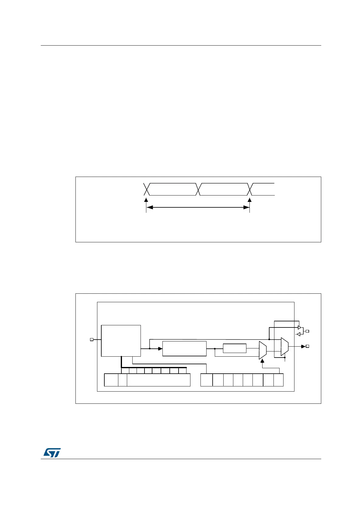
Figure 272 presents the communication clock architecture. The I2Sx clock is always the
system clock.
Figure 272. I
2
S clock generator architecture
1. Where x = 2.
069
RUELWOHIW
FKDQQHO
RUELW
ULJKWFKDQQHO
RUELWV
VDPSOLQJSRLQW
VDPSOLQJSRLQW
)
6
)
6
DXGLRVDPSOLQJIUHTXHQF\
069
0&.2(
2''
ELWOLQHDUGLYLGHU
UHVKDSLQJVWDJH
'LYLGHUE\
'LY
,ð6',9>@
,ð602'
&+/(1
0&.2(
&.
0&.
,ð6[&/.