RM0401 Rev 3 563/771
RM0401 Fast-mode Plus Inter-integrated circuit (FMPI2C) interface
591
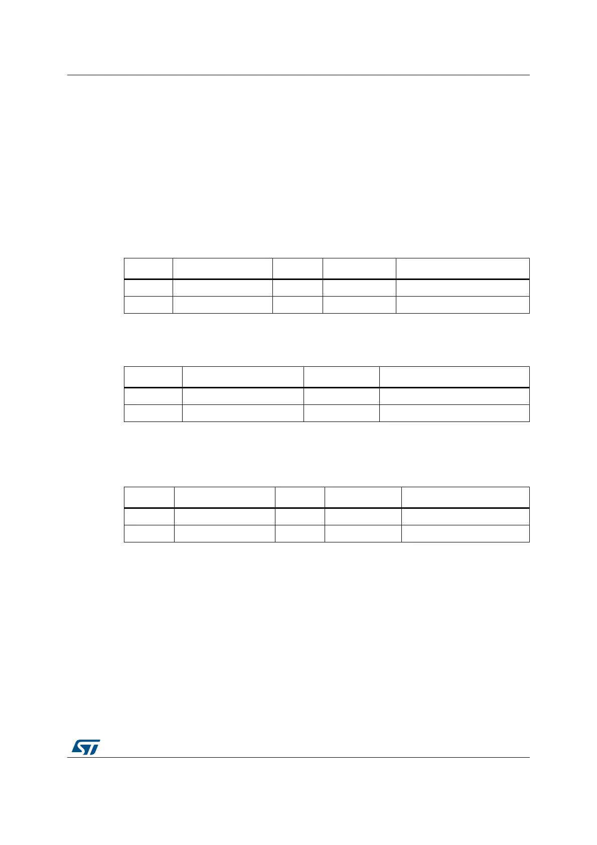
Refer to Table 97: Examples of TIMEOUTA settings for various FMPI2CCLK frequencies
(max tIDLE = 50 µs)
Caution: Changing the TIMEOUTA and TIDLE configuration is not allowed when the TIMEOUTEN is
set.
22.4.13 SMBus: FMPI2C_TIMEOUTR register configuration examples
This section is relevant only when SMBus feature is supported. Refer to Section 22.3:
FMPI2C implementation.
• Configuring the maximum duration of t
TIMEOUT
to 25 ms:
• Configuring the maximum duration of t
LOW:SEXT
and t
LOW:MEXT
to 8 ms:
• Configuring the maximum duration of t
IDLE
to 50 µs
22.4.14 SMBus slave mode
This section is relevant only when SMBus feature is supported. Refer to Section 22.3:
FMPI2C implementation.
In addition to FMPI2C slave transfer management (refer to Section 22.4.8: FMPI2C slave
mode) some additional software flowcharts are provided to support SMBus.
SMBus Slave transmitter
When the IP is used in SMBus, SBC must be programmed to ‘1’ in order to allow the PEC
transmission at the end of the programmed number of data bytes. When the PECBYTE bit
is set, the number of bytes programmed in NBYTES[7:0] includes the PEC transmission. In
that case the total number of TXIS interrupts is NBYTES-1 and the content of the
Table 95. Examples of TIMEOUTA settings for various FMPI2CCLK
frequencies
(max t
TIMEOUT
= 25 ms)
f
I2CCLK
TIMEOUTA[11:0] bits TIDLE bit TIMEOUTEN bit t
TIMEOUT
8 MHz 0x61 0 1 98 x 2048 x 125 ns = 25 ms
16 MHz 0xC3 0 1 196 x 2048 x 62.5 ns = 25 ms
Table 96. Examples of TIMEOUTB settings for various FMPI2CCLK frequencies
f
I2CCLK
TIMEOUTB[11:0] bits TEXTEN bit t
LOW:EXT
8 MHz 0x1F 1 32 x 2048 x 125 ns = 8 ms
16 MHz 0x3F 1 64 x 2048 x 62.5 ns = 8 ms
Table 97. Examples of TIMEOUTA settings for various FMPI2CCLK frequencies
(max t
IDLE
= 50 µs)
f
I2CCLK
TIMEOUTA[11:0] bits TIDLE bit TIMEOUTEN bit t
TIDLE
8 MHz 0x63 1 1 100 x 4 x 125 ns = 50 µs
16 MHz 0xC7 1 1 200 x 4 x 62.5 ns = 50 µs