RM0401 Rev 3 751/771
RM0401 Debug support (DBG)
762
26.15.4 Configuration example
To output a simple value to the TPIU:
1. Configure the TPIU and enable the I/IO_TRACEN to assign TRACE I/Os in the debug
configuration register.
2. Write 0xC5ACCE55 to the ETM Lock Access Register to unlock the write access to the
ITM registers
3. Write 0x00001D1E to the control register (configure the trace)
4. Write 0000406F to the Trigger Event register (define the trigger event)
5. Write 0000006F to the Trace Enable Event register (define an event to start/stop)
6. Write 00000001 to the Trace Start/stop register (enable the trace)
7. Write 0000191E to the ETM Control Register (end of configuration).
26.16 MCU debug component (DBGMCU)
The MCU debug component helps the debugger provide support for:
• Low-power modes
• Clock control for timers, watchdog and I2C during a breakpoint
• Control of the trace pins assignment
26.16.1 Debug support for low-power modes
To enter low-power mode, the instruction WFI or WFE must be executed.
The MCU implements several low-power modes which can either deactivate the CPU clock
or reduce the power of the CPU.
The core does not allow FCLK or HCLK to be turned off during a debug session. As these
are required for the debugger connection, during a debug, they must remain active. The
MCU integrates special means to allow the user to debug software in low-power modes.
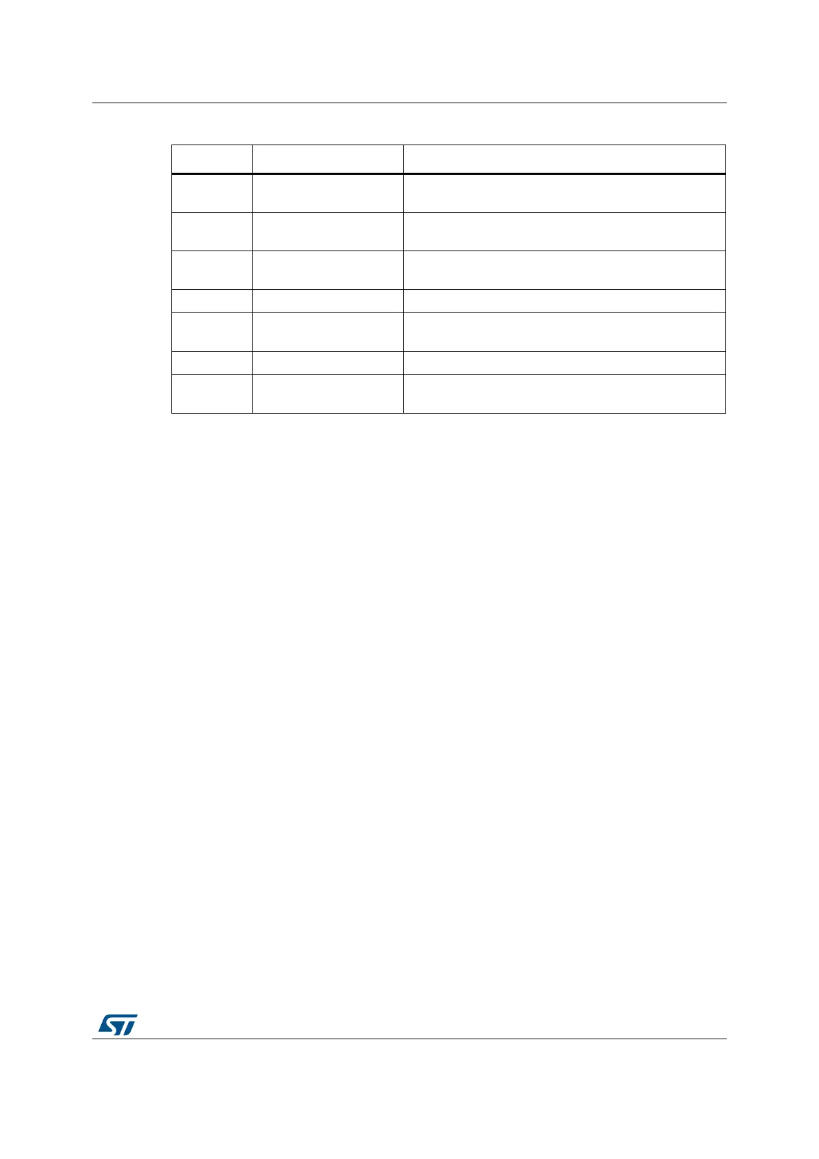
Table 140. Main ETM registers
Address Register Details
0xE0041FB0 ETM Lock Access
Write 0xC5ACCE55 to unlock the write access to the
other ETM registers.
0xE0041000 ETM Control
This register controls the general operation of the ETM,
for instance how tracing is enabled.
0xE0041010 ETM Status
This register provides information about the current status
of the trace and trigger logic.
0xE0041008 ETM Trigger Event This register defines the event that will control trigger.
0xE004101C
ETM Trace Enable
Control
This register defines which comparator is selected.
0xE0041020 ETM Trace Enable Event This register defines the trace enabling event.
0xE0041024 ETM Trace Start/Stop
This register defines the traces used by the trigger source
to start and stop the trace, respectively.