RM0401 Rev 3 457/771
RM0401 Low-power timer (LPTIM)
472
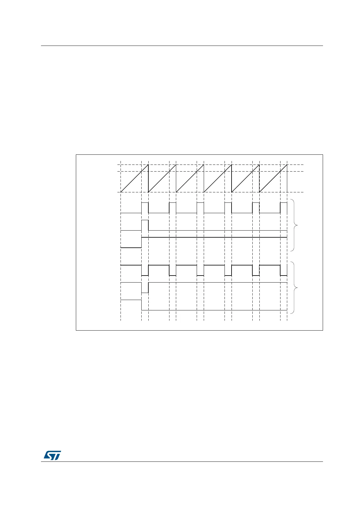
The LPTIM output waveform can be configured through the WAVE bit as follow:
• Resetting the WAVE bit to ‘0’ forces the LPTIM to generate either a PWM waveform or
a One pulse waveform depending on which bit is set: CNTSTRT or SNGSTRT.
• Setting the WAVE bit to ‘1’ forces the LPTIM to generate a Set-once mode waveform.
The WAVPOL bit controls the LPTIM output polarity. The change takes effect immediately,
so the output default value will change immediately after the polarity is re-configured, even
before the timer is enabled.
Signals with frequencies up to the LPTIM clock frequency divided by 2 can be generated.
Figure 171 below shows the three possible waveforms that can be generated on the LPTIM
output. Also, it shows the effect of the polarity change using the WAVPOL bit.
Figure 171. Waveform generation
18.4.11 Register update
The LPTIM_ARR register and LPTIM_CMP register are updated immediately after the APB
bus write operation, or at the end of the current period if the timer is already started.
The PRELOAD bit controls how the LPTIM_ARR and the LPTIM_CMP registers are
updated:
• When the PRELOAD bit is reset to ‘0’, the LPTIM_ARR and the LPTIM_CMP registers
are immediately updated after any write access.
• When the PRELOAD bit is set to ‘1’, the LPTIM_ARR and the LPTIM_CMP registers
are updated at the end of the current period, if the timer has been already started.
The LPTIM APB interface and the LPTIM kernel logic use different clocks, so there is some
latency between the APB write and the moment when these values are available to the
069
/37,0B$55
&RPSDUH
3:0
2QHVKRW
6HWRQFH
3:0
2QHVKRW
6HWRQFH
3RO
3RO