RM0401 Rev 3 283/771
RM0401 Advanced-control timers (TIM1)
339
The repetition counter is decremented:
• At each counter overflow in upcounting mode,
• At each counter underflow in downcounting mode,
• At each counter overflow and at each counter underflow in center-aligned mode.
Although this limits the maximum number of repetition to 128 PWM cycles, it makes it
possible to update the duty cycle twice per PWM period. When refreshing compare
registers only once per PWM period in center-aligned mode, maximum resolution is
2xT
ck
, due to the symmetry of the pattern.
The repetition counter is an auto-reload type; the repetition rate is maintained as defined by
the TIMx_RCR register value (refer to Figure 69). When the update event is generated by
software (by setting the UG bit in TIMx_EGR register) or by hardware through the slave
mode controller, it occurs immediately whatever the value of the repetition counter is and the
repetition counter is reloaded with the content of the TIMx_RCR register.
In center-aligned mode, for odd values of RCR, the update event occurs either on the
overflow or on the underflow depending on when the RCR register was written and when
the counter was started. If the RCR was written before starting the counter, the UEV occurs
on the overflow. If the RCR was written after starting the counter, the UEV occurs on the
underflow. For example for RCR = 3, the UEV is generated on each 4th overflow or
underflow event depending on when RCR was written.
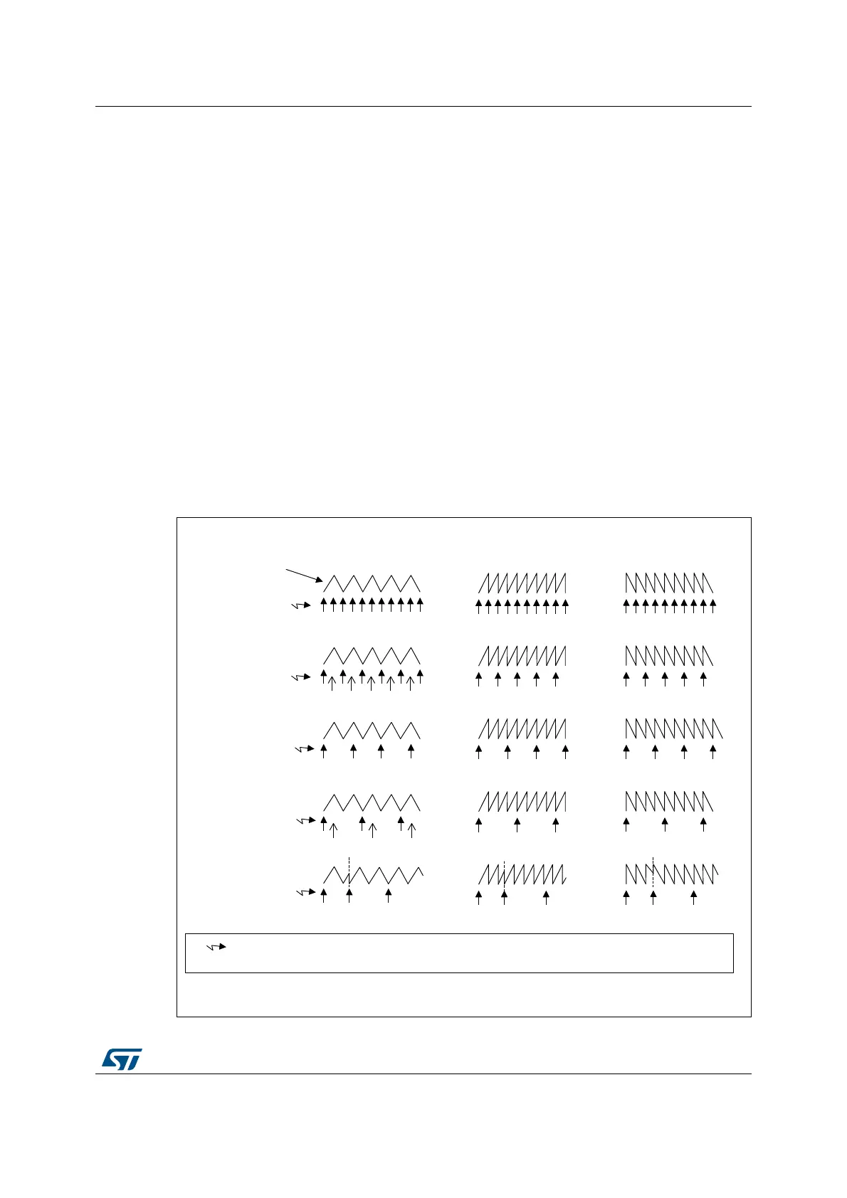
Figure 69. Update rate examples depending on mode and TIMx_RCR register settings
06Y9
8(9
8(9
8(9
8(9
8(9
&RXQWHUDOLJQHGPRGH
(GJHDOLJQHGPRGH
8SFRXQWLQJ 'RZQFRXQWLQJ
E\6:E\6:E\6:
7,0[B5&5
DQG
UHV\QFKURQL]DWLRQ
7,0[B5&5
7,0[B5&5
7,0[B5&5
7,0[B5&5
&RXQWHU
7,0[B&17
8(9
8SGDWHHYHQW3UHORDGUHJLVWHUVWUDQVIHUUHGWRDFWLYHUHJLVWHUVDQGXSGDWHLQWHUUXSWJHQHUDWHG
8SGDWH(YHQWLIWKHUHSHWLWLRQFRXQWHUXQGHUIORZRFFXUVZKHQWKHFRXQWHULVHTXDOWRWKHDXWRUHORDGYDOXH