Inter-integrated circuit (I
2
C) interface RM0401
618/771 RM0401 Rev 3
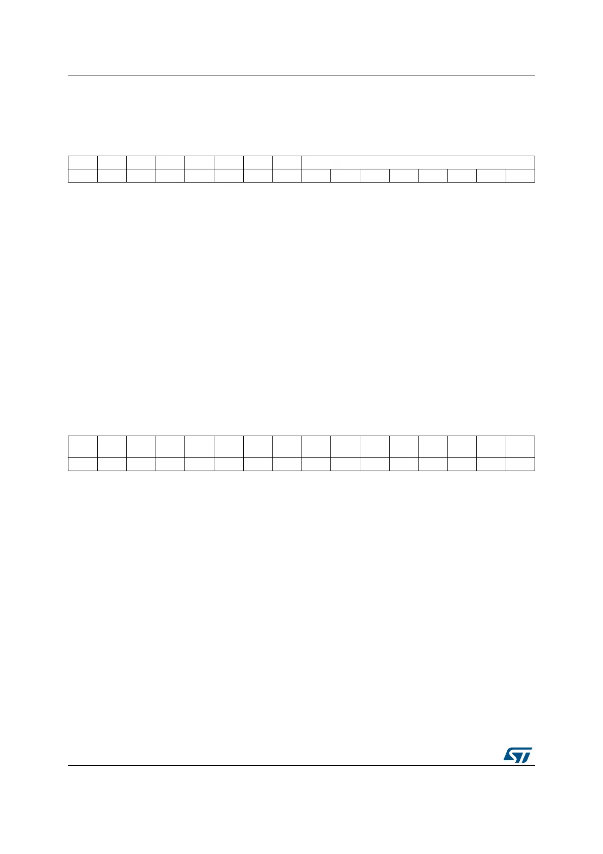
23.6.5 I
2
C Data register (I2C_DR)
Address offset: 0x10
Reset value: 0x0000
23.6.6 I
2
C Status register 1 (I2C_SR1)
Address offset: 0x14
Reset value: 0x0000
1514131211109876543210
Res. Res. Res. Res. Res. Res. Res. Res. DR[7:0]
rw rw rw rw rw rw rw rw
Bits 15:8 Reserved, must be kept at reset value
Bits 7:0 DR[7:0] 8-bit data register
Byte received or to be transmitted to the bus.
– Transmitter mode: Byte transmission starts automatically when a byte is written in the DR
register. A continuous transmit stream can be maintained if the next data to be transmitted is
put in DR once the transmission is started (TxE=1)
– Receiver mode: Received byte is copied into DR (RxNE=1). A continuous transmit stream
can be maintained if DR is read before the next data byte is received (RxNE=1).
Note: In slave mode, the address is not copied into DR.
Write collision is not managed (DR can be written if TxE=0).
If an ARLO event occurs on ACK pulse, the received byte is not copied into DR
and so cannot be read.
1514131211109876543210
SMB
ALERT
TIMEO
UT
Res.
PEC
ERR
OVR AF ARLO BERR TxE RxNE Res. STOPF ADD10 BTF ADDR SB
rc_w0rc_w0 rc_w0rc_w0rc_w0rc_w0rc_w0rr rrrrr