Fast-mode Plus Inter-integrated circuit (FMPI2C) interface RM0401
562/771 RM0401 Rev 3
Timeout detection
The timeout detection is enabled by setting the TIMOUTEN and TEXTEN bits in the
FMPI2C_TIMEOUTR register. The timers must be programmed in such a way that they
detect a timeout before the maximum time given in the SMBus specification.
• t
TIMEOUT
check
In order to enable the t
TIMEOUT
check, the 12-bit TIMEOUTA[11:0] bits must be
programmed with the timer reload value in order to check the t
TIMEOUT
parameter. The
TIDLE bit must be configured to ‘0’ in order to detect the SCL low level timeout.
Then the timer is enabled by setting the TIMOUTEN in the FMPI2C_TIMEOUTR
register.
If SCL is tied low for a time greater than (TIMEOUTA+1) x 2048 x t
I2CCLK
, the TIMEOUT
flag is set in the FMPI2C_ISR register.
Refer to Table 95: Examples of TIMEOUTA settings for various FMPI2CCLK
frequencies (max tTIMEOUT = 25 ms).
Caution: Changing the TIMEOUTA[11:0] bits and TIDLE bit configuration is not allowed when the
TIMEOUTEN bit is set.
• t
LOW:SEXT
and t
LOW:MEXT
check
Depending on if the peripheral is configured as a master or as a slave, The 12-bit
TIMEOUTB timer must be configured in order to check t
LOW:SEXT
for a slave and
t
LOW:MEXT
for a master. As the standard specifies only a maximum, the user can choose
the same value for the both.
Then the timer is enabled by setting the TEXTEN bit in the FMPI2C_TIMEOUTR
register.
If the SMBus peripheral performs a cumulative SCL stretch for a time greater than
(TIMEOUTB+1) x 2048 x t
I2CCLK
, and in the timeout interval described in Bus idle
detection on page 561 section, the TIMEOUT flag is set in the FMPI2C_ISR register.
Refer to Table 96: Examples of TIMEOUTB settings for various FMPI2CCLK
frequencies
Caution: Changing the TIMEOUTB configuration is not allowed when the TEXTEN bit is set.
Bus Idle detection
In order to enable the t
IDLE
check, the 12-bit TIMEOUTA[11:0] field must be programmed
with the timer reload value in order to obtain the t
IDLE
parameter. The TIDLE bit must be
configured to ‘1 in order to detect both SCL and SDA high level timeout.
Then the timer is enabled by setting the TIMOUTEN bit in the FMPI2C_TIMEOUTR register.
If both the SCL and SDA lines remain high for a time greater than (TIMEOUTA+1) x 4 x
t
I2CCLK
, the TIMEOUT flag is set in the FMPI2C_ISR register.
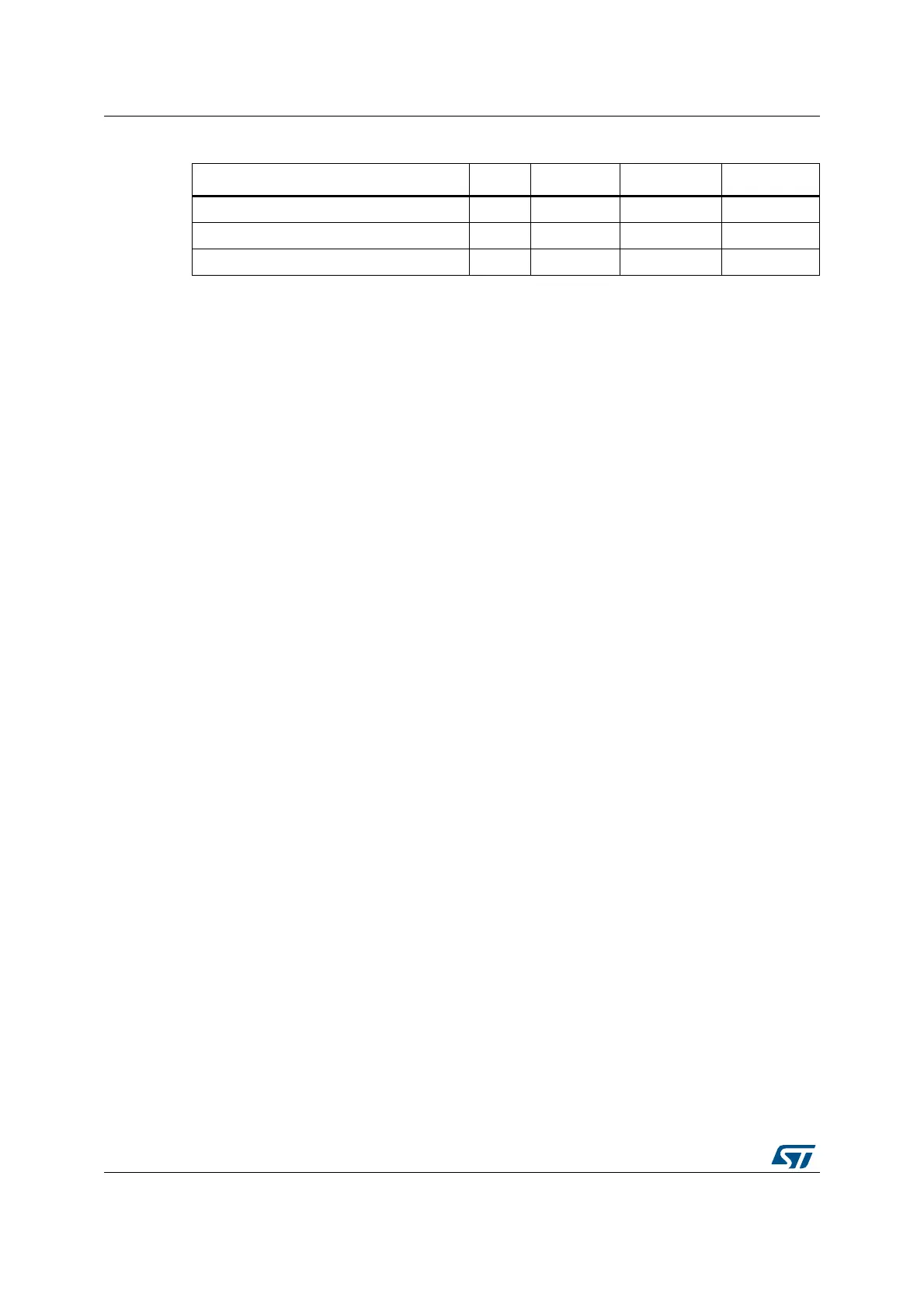
Table 94. SMBUS with PEC configuration
Mode SBC bit RELOAD bit AUTOEND bit PECBYTE bit
Master Tx/Rx NBYTES + PEC+ STOP x 0 1 1
Master Tx/Rx NBYTES + PEC + ReSTART x 0 0 1
Slave Tx/Rx with PEC 1 0 x 1