Universal synchronous receiver transmitter (USART) /universal asynchronous receiver transmit-
654/771 RM0401 Rev 3
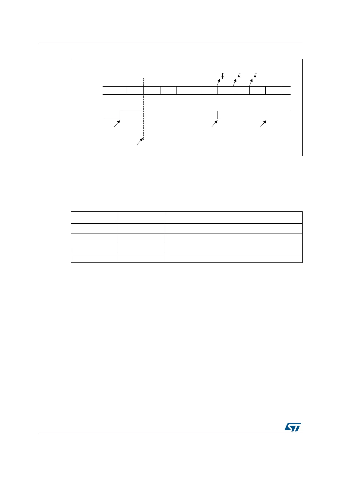
Figure 222. Mute mode using address mark detection
24.4.7 Parity control
Parity control (generation of parity bit in transmission and parity checking in reception) can
be enabled by setting the PCE bit in the USART_CR1 register. Depending on the frame
length defined by the M bit, the possible USART frame formats are as listed in Table 121.
Even parity
The parity bit is calculated to obtain an even number of “1s” inside the frame made of the 7
or 8 LSB bits (depending on whether M is equal to 0 or 1) and the parity bit.
E.g.: data=00110101; 4 bits set => parity bit will be 0 if even parity is selected (PS bit in
USART_CR1 = 0).
Odd parity
The parity bit is calculated to obtain an odd number of “1s” inside the frame made of the 7 or
8 LSB bits (depending on whether M is equal to 0 or 1) and the parity bit.
E.g.: data=00110101; 4 bits set => parity bit will be 1 if odd parity is selected (PS bit in
USART_CR1 = 1).
Parity checking in reception
If the parity check fails, the PE flag is set in the USART_SR register and an interrupt is
generated if PEIE is set in the USART_CR1 register. The PE flag is cleared by a software
06Y9
,'/( $GGU 'DWD 'DWD ,'/( $GGU 'DWD 'DWD $GGU 'DWD
,QWKLVH[DPSOHWKHFXUUHQWDGGUHVVRIWKHUHFHLYHULV
SURJUDPPHGLQWKH86$57B&5UHJLVWHU
5;1(
1RQPDWFKLQJDGGUHVV0DWFKLQJDGGUHVV
1RQPDWFKLQJDGGUHVV
0054ZULWWHQWR
5;1(ZDVFOHDUHG
5:8
5;
0XWHPRGH 0XWHPRGH1RUPDOPRGH
5;1( 5;1(
Table 121. Frame formats
M bit PCE bit USART frame
(1)
1. Legends: SB: start bit, STB: stop bit, PB: parity bit.
0 0 | SB | 8 bit data | STB |
0 1 | SB | 7-bit data | PB | STB |
1 0 | SB | 9-bit data | STB |
1 1 | SB | 8-bit data PB | STB |