GUID-6E07E5DC-9779-45C6-B12C-678AF3E33BA3
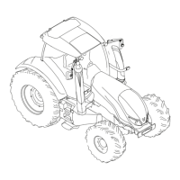
1. Not in use
2. CAN L
3. Not in use
4. CAN H
5. Not in use
6. Power supply for terminating bias circuit (TBC PWR)
7. Power supply for electronic control unit (ECU PWR)
8. Ground for terminating bias circuit (TBC GND)
9. Ground for electronic control unit (ECU GND)
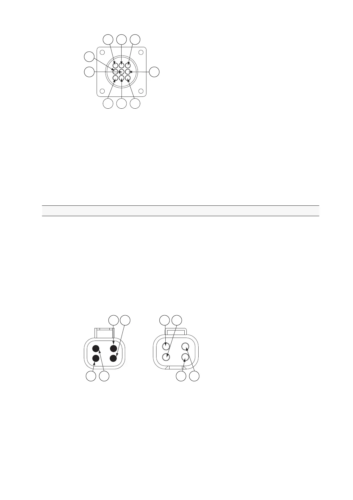
3.19.3 Bus extension connectors
Bus extension connectors are part of the ISOBUS implement control system
(extra equipment). Normally the bus extension connectors are connected
together. They can also be used to connect additional ISOBUS devices to
ISOBUS (for example, ISOBUS GPS).
NOTE: If the bus extension connectors are disconnected, the ISOBUS implement
bus is broken and the system does not function properly. When connecting
additional ISOBUS devices, check that the bus stays intact (the bus extension
connectors are connected).
The connectors are located behind the cover, inside the B-pillar.
GUID-F19C60D2-B673-43DA-B723-EBCD7C76C681
1. Power supply for terminating bias circuit (TBC PWR)
2. CAN H
3. Return path for terminating bias circuit (TBC RTN)
4. CAN L
3. Operation
- 211 -

 Loading...