• Distance based on information of the radar
• Distance based on tyre rotation
• Driving direction based on the power shuttle lever position
• Front linkage and front PTO
• Front PTO speed
• Front PTO engagement
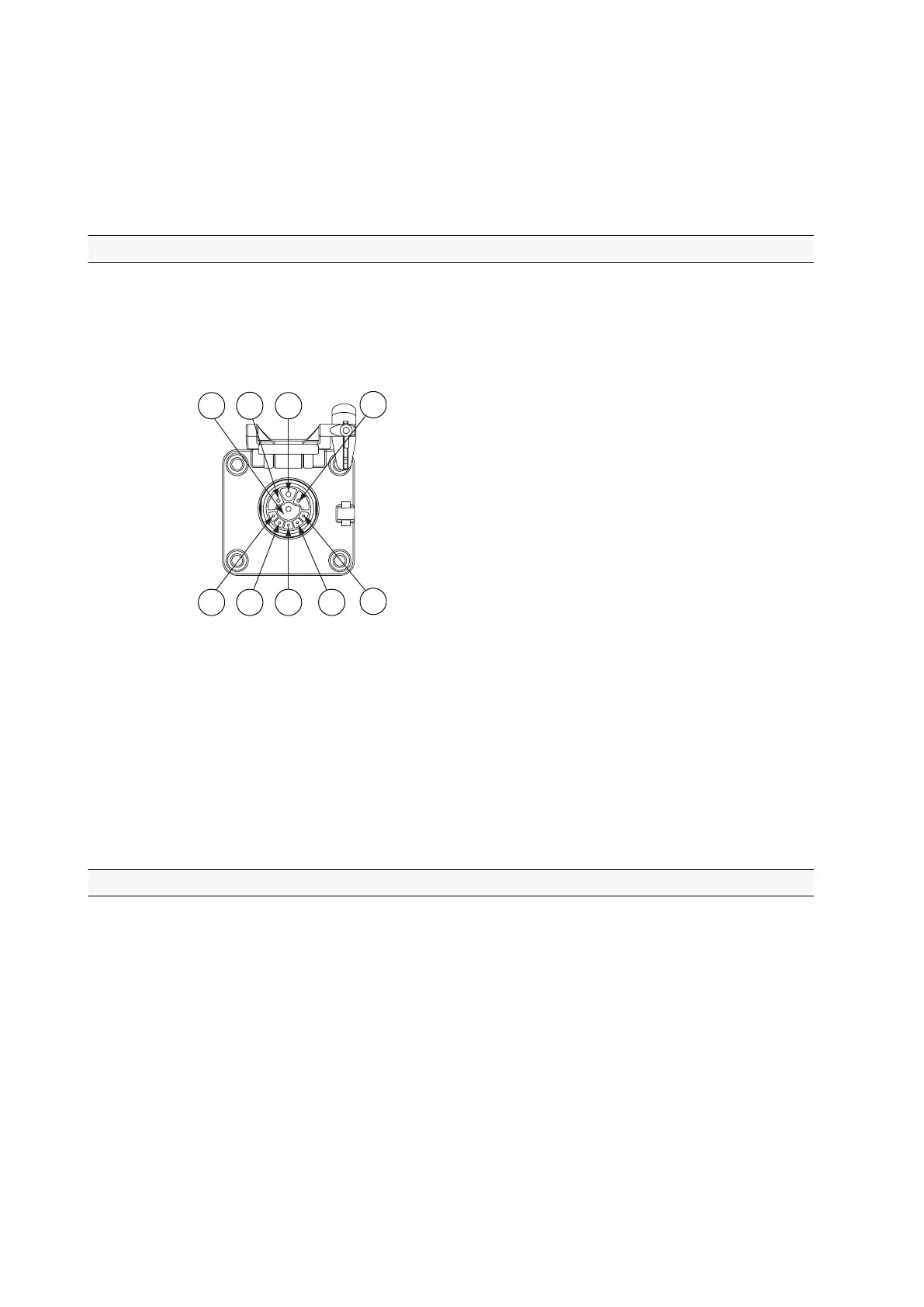
3.19.1 ISOBUS implement connector
The ISOBUS implement connector is part of the ISOBUS implement control
system (extra equipment). The connector connects an ISOBUS compatible
implement to the ISOBUS system.
An extra connector is available with front linkage.
GUID-7595B300-8E9C-4545-9298-D38D3FEC87B2
1. Ground (GND)
2. Power supply for electronic control unit max. 15 A (ECU PWR)
3. Power supply max. 30 A (PWR)
4. Electronic control unit ground (ECU GND)
5. Not in use
6. Power supply for terminating bias circuit (TBC PWR)
7. Return path for terminating bias circuit (TBC RTN)
8. CAN H
9. CAN L
3.19.2 ISOBUS terminal connector
The ISOBUS terminal connector is part of the ISOBUS implement control system
(extra equipment). The connector is used to connect the terminal to the ISOBUS
system.
The connector includes both an ISOBUS data bus and a power supply.
3. Operation
- 210 -

 Loading...