228 Modbus – e!RUNTIME WAGO-I/O-SYSTEM 750
750-8100 PFC100; 2ETH; ECO
Manual
Version 1.6.0, valid from FW Version 03.02.02(14)
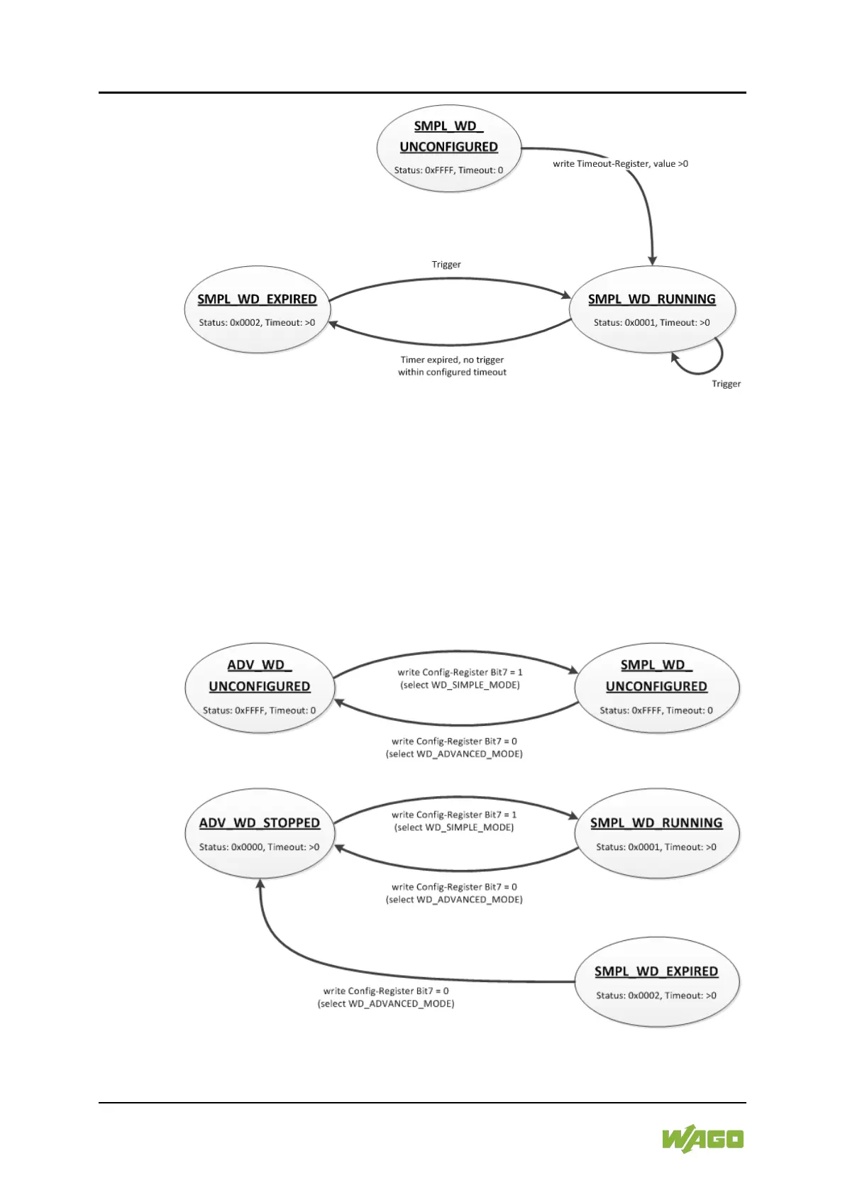
Figure 44: State Diagram, SIMPLE_WATCHDOG Operation Mode
The state diagram for the SIMPLE_WATCHDOG operation mode shows that the
watchdog is always active as soon as a timeout > 0 is set in the register 0xFA01
(Watchdog Timeout). The writing of commands in the register 0xFA00 (Watchdog
Command) is restricted in this operation mode. Only the WATCHDOG_START
command is permitted as a possible trigger. The only possibility to deactivate and
stop the watchdog in operation mode SIMPLE_WATCHDOG, is the switching
back to the operation mode ADVANCED_WATCHDOG.
The following diagram shows the possible state transitions when operation
modes are switched.