WAGO-I/O-SYSTEM 750 Appendix 295
750-8100 PFC100; 2ETH; ECO
Manual
Version 1.6.0, valid from FW Version 03.02.02(14)
750-634
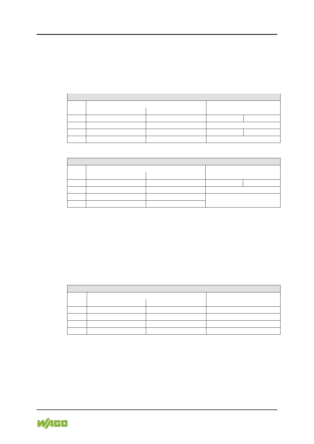
The above Incremental Encoder Interface module has 5 bytes of input data (6
bytes in cycle duration measurement mode) and 3 bytes of output data. The
following tables illustrate the Input and Output Process Image, which has 4 words
mapped into each image. Word alignment is applied.
Table 245: Incremental Encoder Interface Modules 750-634
*) If cycle duration measurement mode is enabled in the control byte, the cycle duration is given as a 24-bit value that is stored
in D2 together with D3/D4.
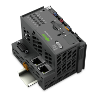
750-637, (and all variations)
The above Incremental Encoder Interface Module has a total of 6 bytes of user
data in both the Input and Output Process Image (4 bytes of encoder data and 2
bytes of control/status). The following table illustrates the Input and Output
Process Image, which have 4 words mapped into each image. Word alignment is
applied.
Table 246: Incremental Encoder Interface Modules 750-637, (and all variations)
Input and Output Process Image
Control/Status byte of Channel 1
Control/Status byte of Channel 2