72 Mounting WAGO-I/O-SYSTEM 750
750-8100 PFC100; 2ETH; ECO
Manual
Version 1.6.0, valid from FW Version 03.02.02(14)
5.3.2 WAGO DIN Rails
WAGO carrier rails meet the electrical and mechanical requirements shown in the
table below.
35 × 7.5; 1 mm; steel; bluish, tinned, chromed; slotted
35 × 7.5; 1 mm; steel; bluish, tinned, chromed; unslotted
35 × 15; 1.5 mm; steel; bluish, tinned, chromed; slotted
35 × 15; 1.5 mm; steel; bluish, tinned, chromed; unslotted
35 × 15; 2.3 mm; steel; bluish, tinned, chromed; unslotted
35 × 15; 2.3 mm; copper; unslotted
35 × 8.2; 1.6 mm; aluminum; unslotted
Observe the mounting distance of the DIN rail when the load is increased!
With increased vibration and shock load, mount the DIN rail at a mounting
distance of max. 60 mm.
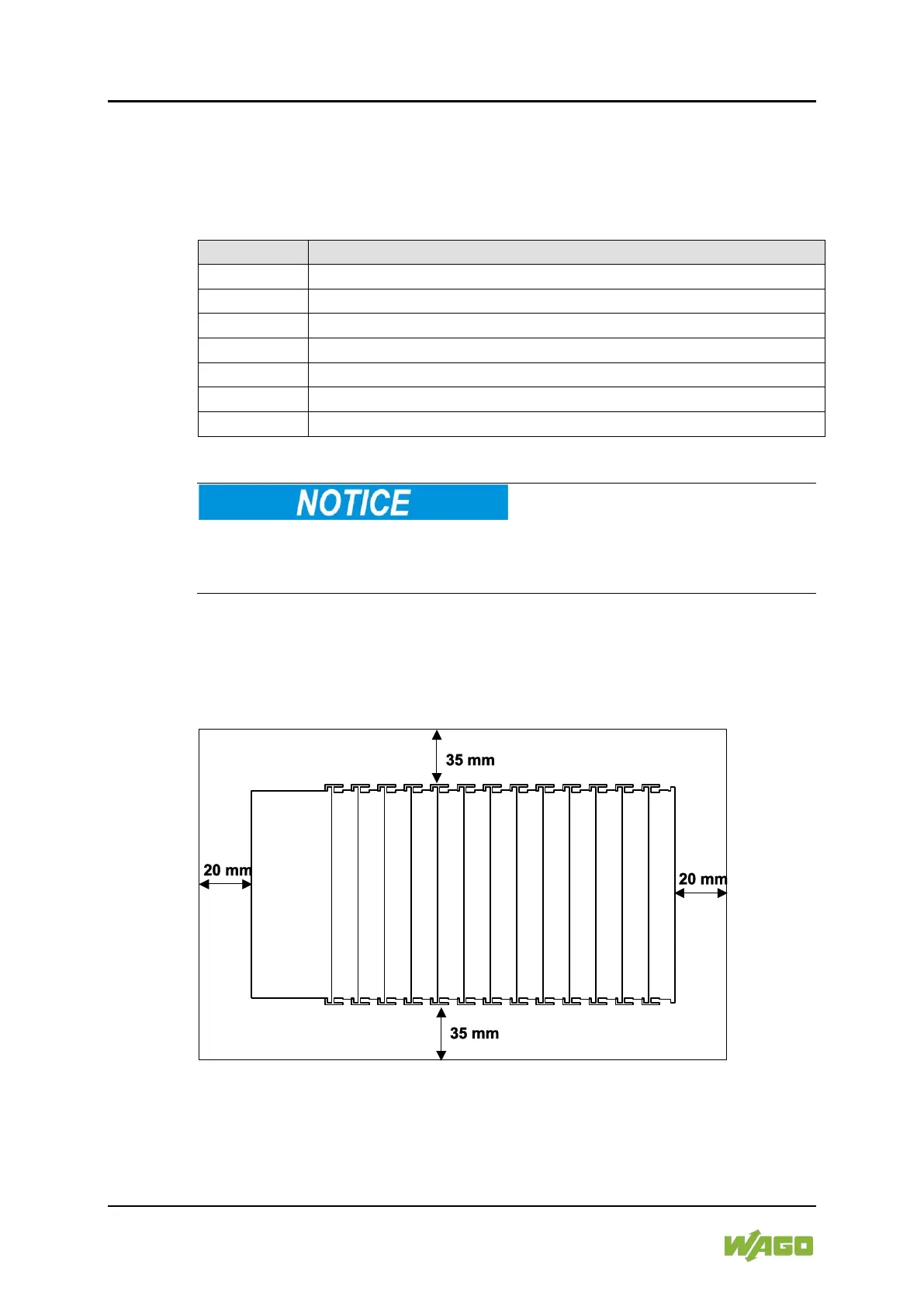
5.4 Spacing
The spacing between adjacent components, cable conduits, casing and frame
sides must be maintained for the complete fieldbus node.
Figure 16: Spacing
The spacing creates room for heat transfer, installation or wiring. The spacing to
cable conduits also prevents conducted electromagnetic interferences from
influencing the operation.