272 Appendix WAGO-I/O-SYSTEM 750
750-8100 PFC100; 2ETH; ECO
Manual
Version 1.6.0, valid from FW Version 03.02.02(14)
15.1.1.4 2 Channel Digital Input Module with Diagnostics and Output Process
Data
750-418,
753-418
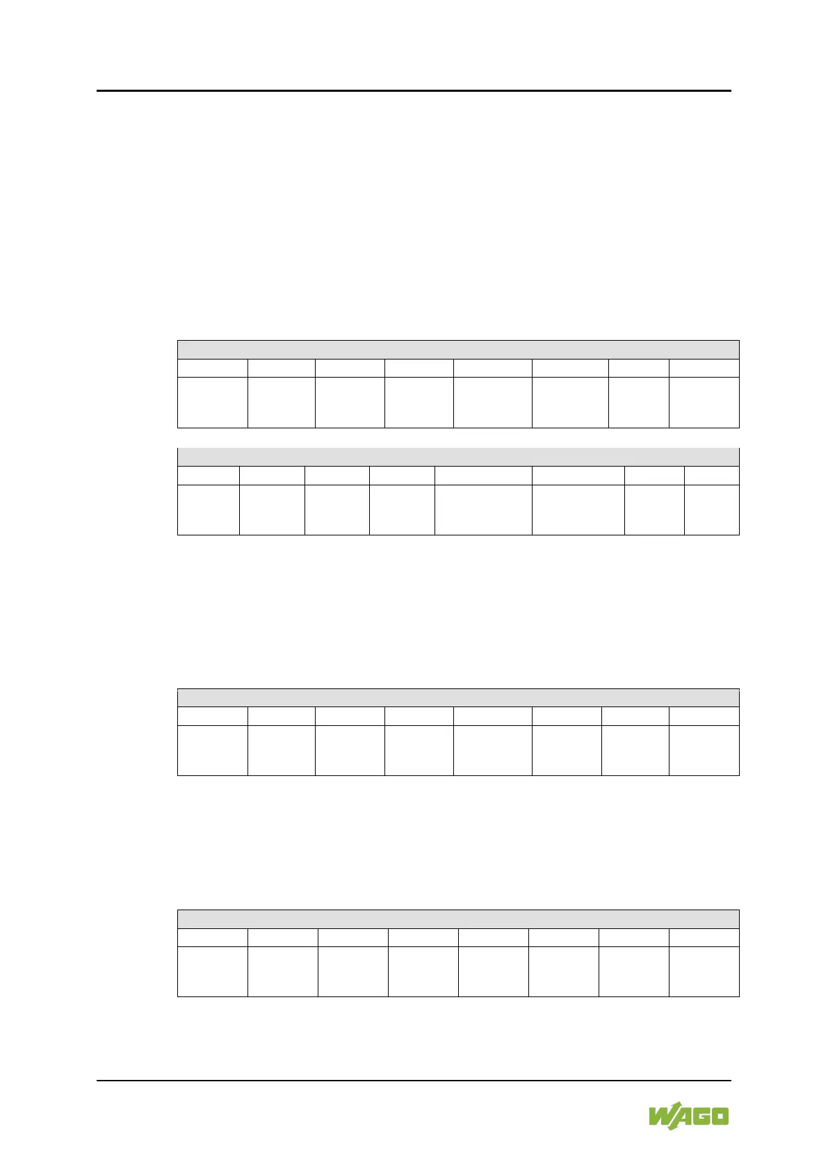
The digital input module supplies a diagnostic and acknowledge bit for each input
channel. If a fault condition occurs, the diagnostic bit is set. After the fault
condition is cleared, an acknowledge bit must be set to re-activate the input. The
diagnostic data and input data bit is mapped in the Input Process Image, while
the acknowledge bit is in the Output Process Image.
Table 207: 2 Channel Digital Input Module with Diagnostics and Output Process Data
Diagnostic bit
S 2
Channel 2
Diagnostic bit
S 1
Channel 1
Acknowledge-
ment bit Q 2
Channel 2
Acknowledge-
ment bit Q 1
Channel 1
15.1.1.5 4 Channel Digital Input Modules
750-402, -403, -408, -409, -414, -415, -422, -423, -428, -432, -433, -1420, -1421,
-1422, -1423
753-402, -403, -408, -409, -415, -422, -423, -428, -432, -433, -440
Table 208: 4 Channel Digital Input Modules
15.1.1.6 8 Channel Digital Input Modules
750-430, -431, -436, -437, -1415, -1416, -1417, -1418,
753-430, -431, -434, -436, -437
Table 209: 8 Channel Digital Input Modules