WAGO-I/O-SYSTEM 750 Appendix 277
750-8100 PFC100; 2ETH; ECO
Manual
Version 1.6.0, valid from FW Version 03.02.02(14)
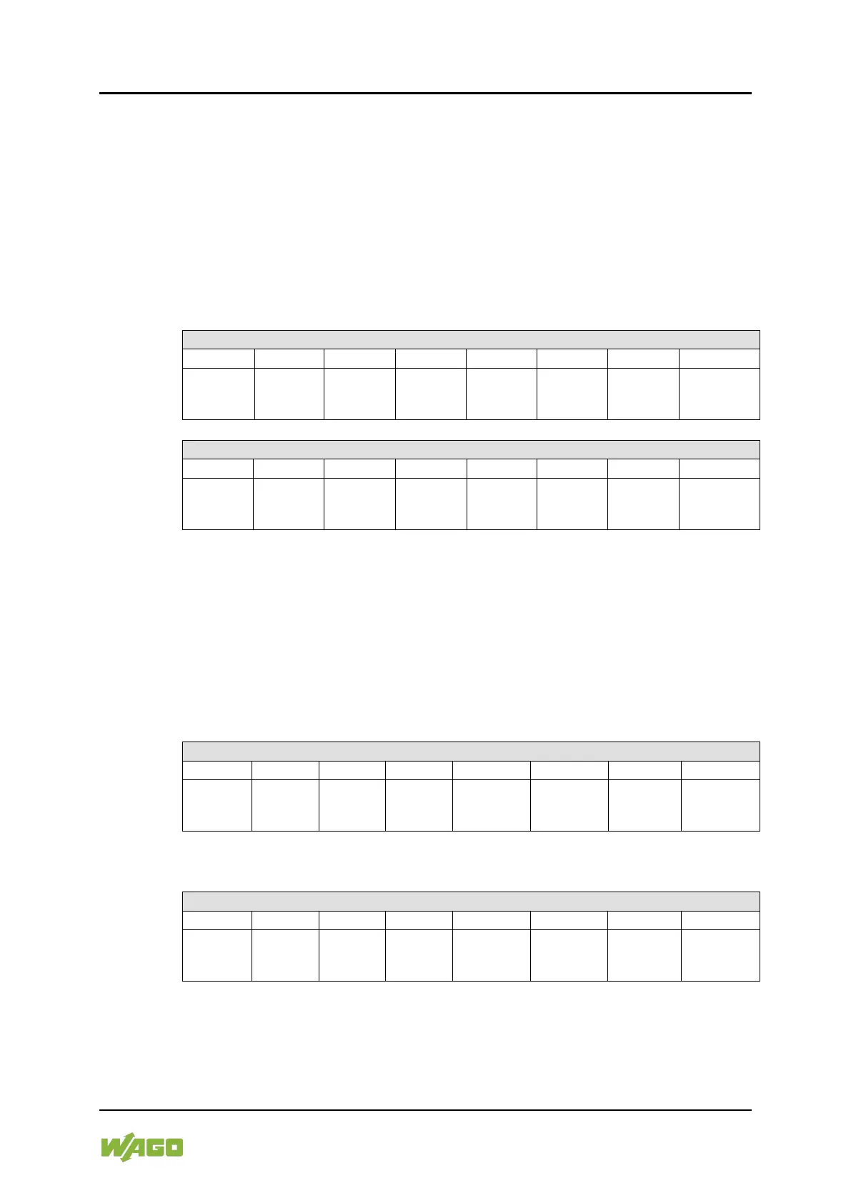
15.1.2.4 2 Channel Digital Input Modules with Diagnostics and Input Process
Data
750-507 (-508), -522,
753-507
The digital output modules have a diagnostic bit for each output channel. When
an output fault condition occurs (i.e., overload, short circuit, or broken wire), a
diagnostic bit is set. The diagnostic data is mapped into the Input Process Image,
while the output control bits are in the Output Process Image.
Table 215: 2 Channel Digital Input Modules with Diagnostics and Input Process Data
Diagnostic
bit S 2
Channel 2
Diagnostic
bit S 1
Channel 1
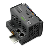
750-506,
753-506
The digital output module has 2-bits of diagnostic information for each output
channel. The 2-bit diagnostic information can then be decoded to determine the
exact fault condition of the module (i.e., overload, a short circuit, or a broken
wire). The 4-bits of diagnostic data are mapped into the Input Process Image,
while the output control bits are in the Output Process Image.
Table 216: 2 Channel Digital Input Modules with Diagnostics and Input Process Data 75x-506
Diagnostic
bit S 3
Channel 2
Diagnostic
bit S 2
Channel 2
Diagnostic
bit S 1
Channel 1
Diagnostic
bit S 0
Channel 1
Diagnostic bits S1/S0, S3/S2: = ‘00’ standard mode
Diagnostic bits S1/S0, S3/S2: = ‘01’ no connected load/short circuit against +24 V
Diagnostic bits S1/S0, S3/S2: = ‘10’ Short circuit to ground/overload