ENGINE
M6040, M7040, WSM
1-M11
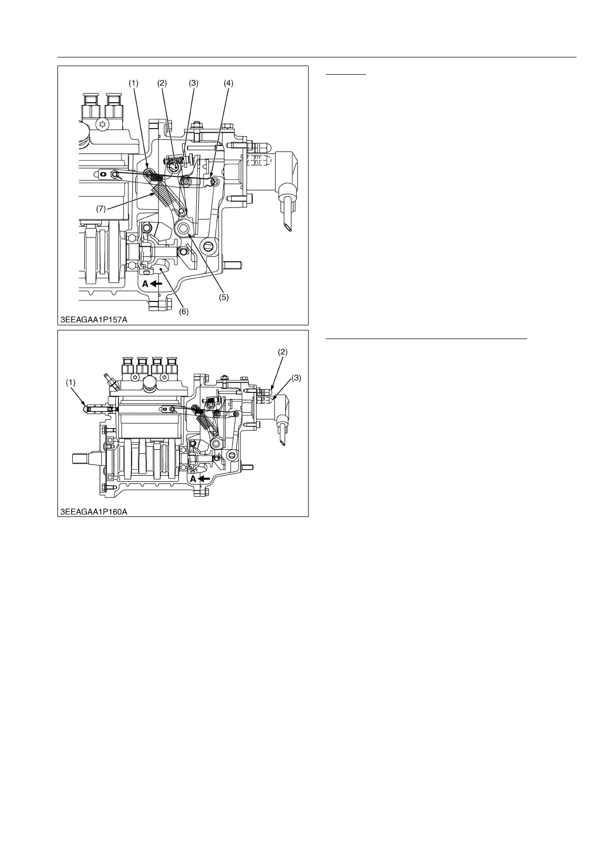
At Idling
Turn the speed control lever (2) clockwise to idle the
engine. It tensions the governor spring (7) to pull the fork
lever 2 (1).
When the fork lever 2 is pulled, it moves the torque
spring pin (3) and the fork lever 1 (5) in the direction of
the arrow "A" to restrain the weight. In combination with
the start spring tension, it is balanced with the centrifugal
force of flywheel weight to keep idling.
9Y1210143ENM0017US0
At rated speed with full load and overload
As the speed control lever is changed from the
middle speed to high speed, the governor spring tension
increases to compress the torque spring and move the
fork lever 1 in the direction of the arrow "A".
The fork lever 2 moves until it reaches the output
limiting bolt to keep rated rotation and rated output.
When the engine is overloaded, the engine rotating
speed decreases and the centrifugal force of flywheel
weight decreases. Then the torque spring moves the
fork lever 1 in the direction of arrow "A".
The control rack moves in the direction that
increases fuel supply to increase the output. It is
balanced with the centrifugal force of the flywheel weight
to produce low-speed output (torque output).
9Y1210143ENM0018US0
(1) Fork Lever 2
(2) Speed Control Lever
(3) Spring Pin
(4) Start Spring
(5) Fork Lever 1
(6) Flyweight
(7) Governor Spring
(1) No-load Maximum Rotation
(2) Output Limiting Bolt
(3) Torque Limiting Bolt