ENGINE
M6040, M7040, WSM
1-S75
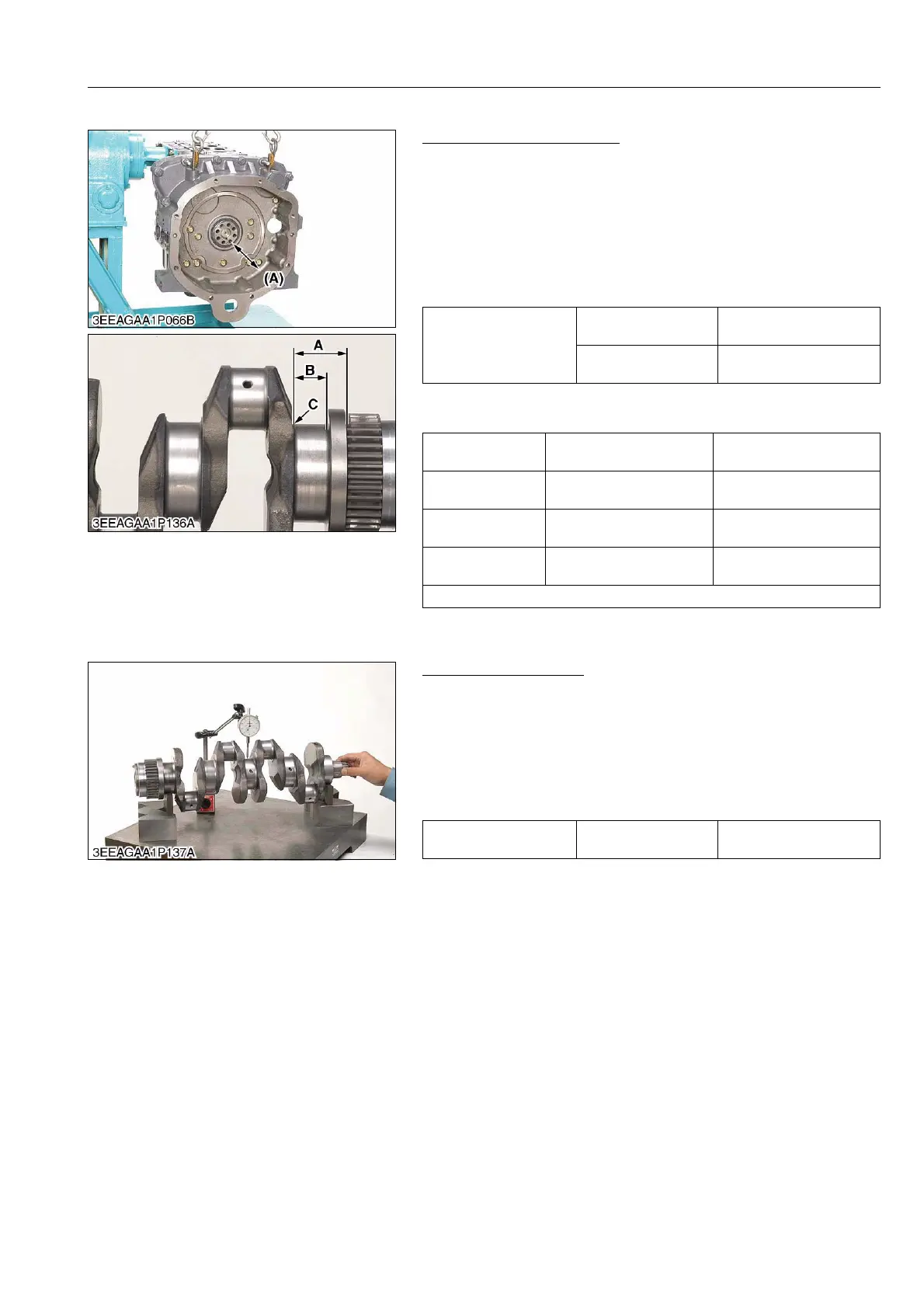
(4) Crankshaft
Crankshaft Side Clearance
1. Set a dial indicator with its tip on the end of the crankshaft.
2. Measure the side clearance by moving the crankshaft to the
front and rear.
3. If the measurement exceeds the allowable limit, replace the
thrust bearings.
4. If the same size bearing is out of specifications because of the
crankshaft journal wear, replace it with an oversize one referring
to the table and figure.
(Reference)
• Oversize dimensions of crankshaft journal.
9Y1210143ENS0120US0
Crankshaft Alignment
1. Support the crankshaft with V block on the surface plate and set
a dial indicator with its tip on the intermediate journal at right
angle.
2. Rotate the crankshaft on the V block and get the misalignment
(half of the measurement value).
3. If the misalignment exceeds the allowable limit, replace the
crankshaft.
9Y1210143ENS0121US0
Side clearance of
crankshaft
Factory specification
0.15 to 0.35 mm
0.0059 to 0.0138 in.
Allowable limit
0.50 mm
0.0197 in.
Oversize
0.20 mm
0.0079 in.
0.40 mm
0.016 in.
Dimension A
41.10 to 42.10 mm
1.619 to 1.657 in.
41.20 to 42.20 mm
1.622 to 1.661 in.
Dimension B
28.20 to 28.25 mm
1.111 to 1.112 in.
28.40 to 28.45 mm
1.1191 to 1.120 in.
Dimension C
2.8 to 3.2 mm radius
0.11 to 0.12 in. radius
2.8 to 3.2 mm radius
0.11 to 0.12 in. radius
The crankshaft journal must be fine-finished to higher than Rmax = 0.8S.
(A) Side Clearance of Crankshaft
Crankshaft alignment Allowable limit
0.02 mm
0.00079 in.