TRANSMISSION
M6040, M7040, WSM
3-S12
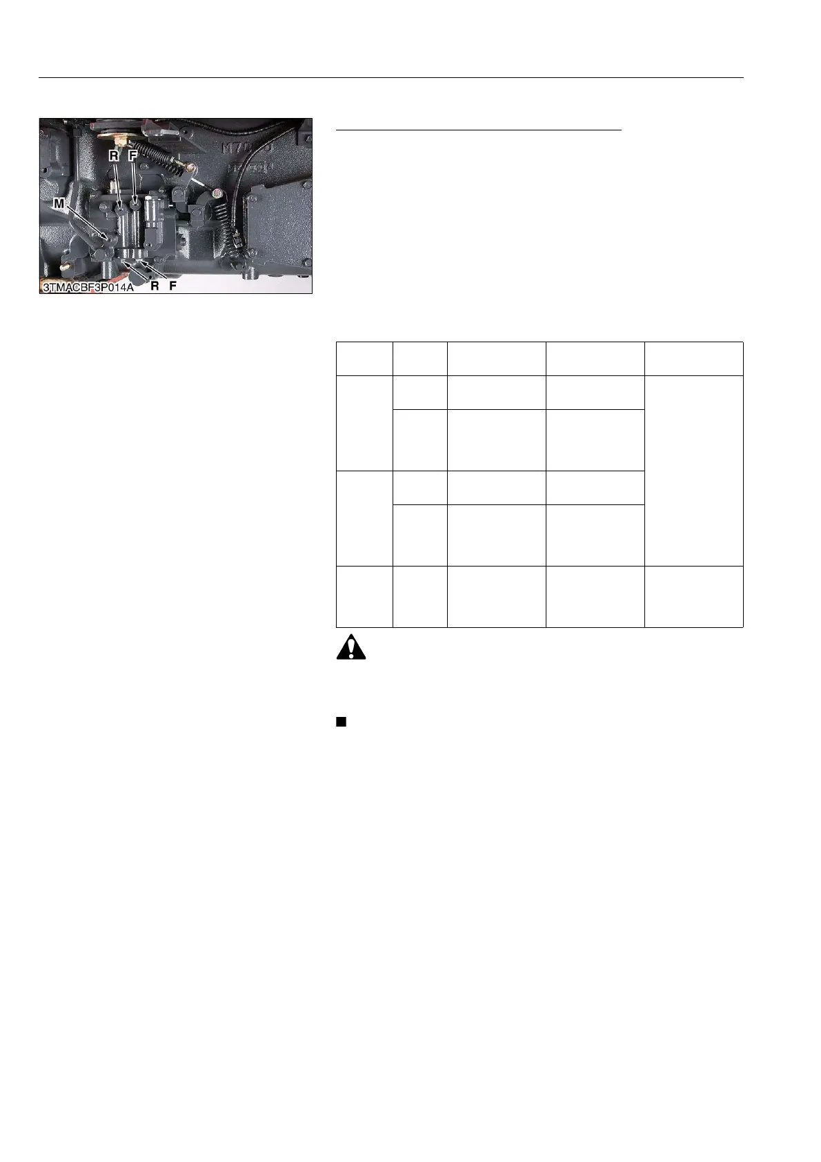
[3] SHUTTLE VALVE
Checking of Shuttle Valve System Pressure
1. Prepare a can for fuel, place in the fuel and fuel return hose into
a can.
2. Remove the plugs of F, R, M and install the adaptor (see page
G-70), threaded joint, cable, and pressure gauge (Code No.:
07916-52961).
3. Start the engine and measure the pressure of each port and
each shuttle lever position as the pressure table.
Condition
• Engine speed
Approx. 2600 min
-1
(rpm)
• Oil temperature
45 to 55 °C (113 to 131 °F)
• Be sure to place the main gear shift lever in neutral and set
the brake pedals to parking brake position, when check the
shuttle valve system pressure.
• Pressure gauge is 5 MPa (50 kgf/cm
2
, 700 psi) full scale.
• Apply Three Bond 1324N or equivalent to the plugs F, R and
M, when install them.
• Plug (F, R, M) thread size is R1/8.
9Y1210143TRS0009US0
Shuttle
Lever
Clutch
Pedal
F port pressure R port pressure M port pressure
Forward
Fully
pressed
00
2.16 to 2.25 MPa
22.0 to
23.0 kgf/cm
2
313 to 327 psi
Free
2.06 to 2.26 MPa
21 to 23 kgf/cm
2
298.7 to
327.1 psi
0
Reverse
Fully
pressed
00
Free 0
2.06 to 2.26 MPa
21 to 23 kgf/cm
2
298.7 to
327.1 psi
Neutral – 0 0
0.26 to 0.28 MPa
2.7 to
2.9 kgf/cm
2
38 to 41 psi
Plug F: Operation Oil Pressure
(For Forward)
Plug R: Operation Oil Pressure
(For Reverse)
Plug M: Operation Oil Pressure
(For Modulation Valve)