ELECTRICAL SYSTEM
M6040, M7040, WSM
9-S47
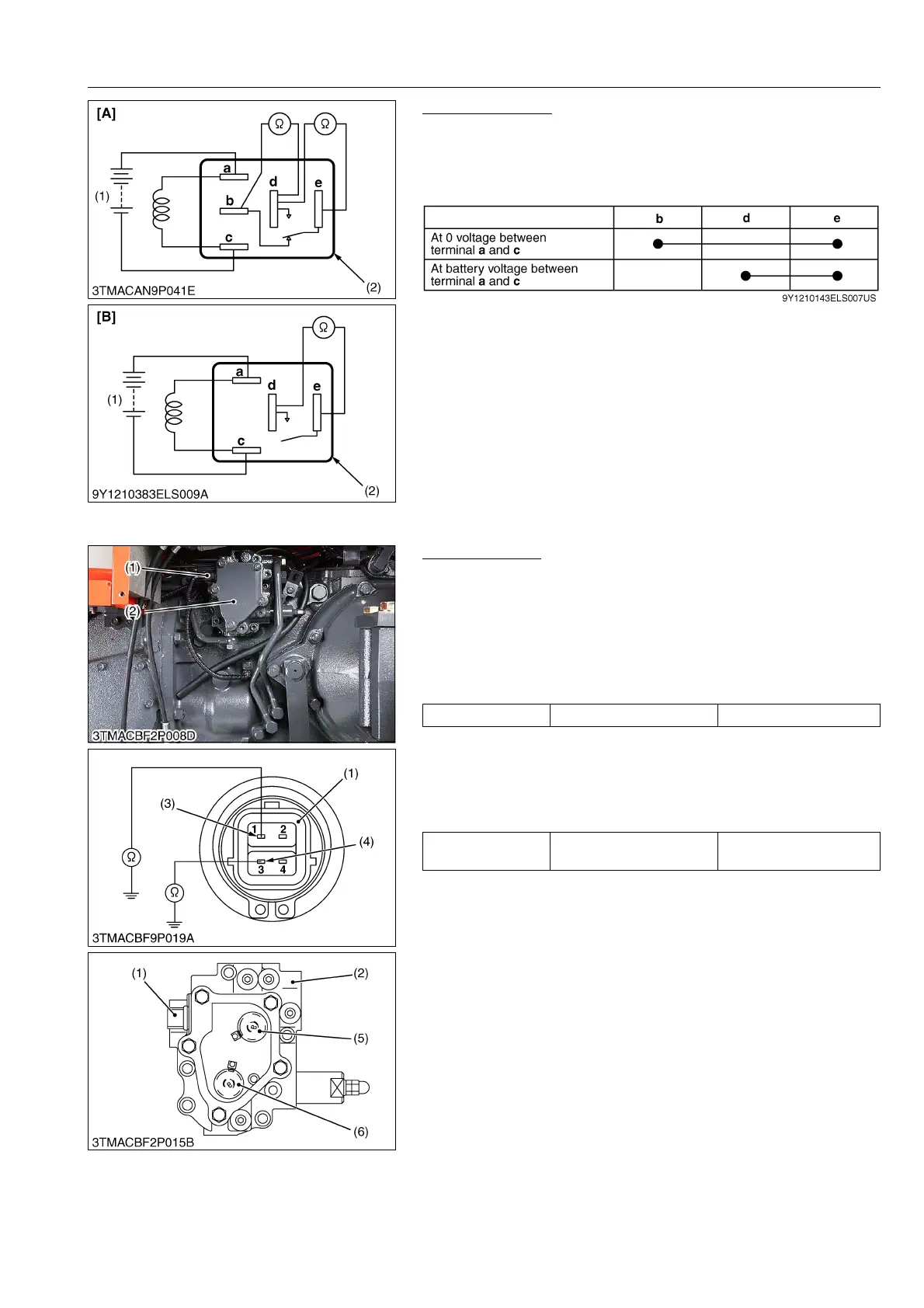
Functional Check
1. Apply battery voltage across the terminals a and c, and check
for continuity across the terminals d and e.
2. If continuity is not established across terminals d and e, replace
it.
9Y1210143ELS0075US0
[10] SOLENOID VALVE
Solenoid Valves
1) Connector Voltage
1. Remove the connector (1).
2. Turn on the main switch, PTO switch or 4WD switch at ON
position.
3. Measure the voltage across the each terminal and chassis.
4. If the voltage differs from battery voltage, the wiring harness,
fuse or main switch is faulty.
2) Solenoid Valve
1. Disconnect the wire harness connector (1).
2. Measure the resistance with an ohmmeter across the each
terminal 1/3 on the connector (1) and chassis.
3. If infinity is indicated, the solenoid valve is faulty.
9Y1210143ELS0076US0
(1) Battery
(2) Connector (Relay)
[A] 5 Terminal Type
[B] 4 Terminal Type
Voltage Each terminal – Chassis Approx. battery voltage
Resistance
Solenoid valve 1/3 terminal
to chassis
10 to 12 Ω
(1) Connector
(2) Solenoid Valve Assembly
(3) Terminal 1 for 4WD Solenoid Valve
(4) Terminal 3 for PTO Solenoid Valve
(5) 4WD Solenoid Valve
(6) PTO Solenoid Valve