TRANSMISSION
M6040, M7040, WSM
3-S29
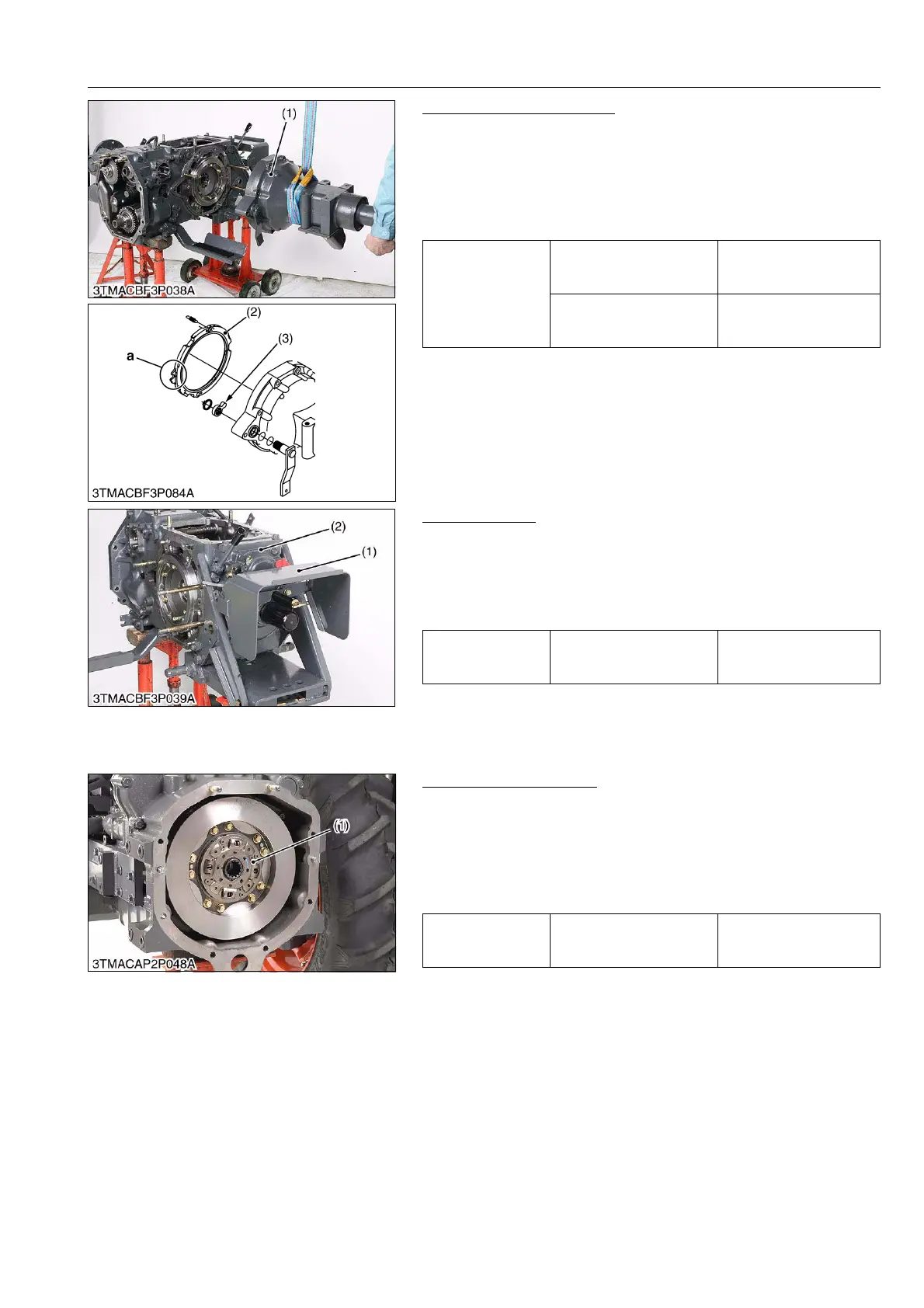
Removing Rear Axle Case
1. Remove the rear axle case mounting screws and nuts.
2. Remove the rear axle case assembly (1).
(When reassembling)
• Apply liquid gaskets (Three Bond 1206C or equivalent) to joint
face.
• Align the brake cam (3) and groove "a" of brake cam plate (2).
9Y1210143TRS0051US0
PTO Gear Case
1. Remove the PTO cover (1).
2. Remove the PTO gear case assembly (2).
(When reassembling)
• Apply liquid gaskets (Three Bond 1206C or equivalent) to joint
face.
9Y1210143TRS0052US0
[6] DAMPER DISC
Removing Damper Disc
1. Remove the damper disc (1).
(When reassembling)
• Direct the shorter end of the damper disc boss toward the
flywheel.
• Apply molybdenum disulphide (Three Bond 1901 or equivalent)
to the spline.
9Y1210143TRS0053US0
Tightening torque
Rear axle mounting screw
(M14, 9T)
166.7 to 196.1 N·m
17.0 to 20.0 kgf·m
123.0 to 144.3 lbf·ft
Rear axle mounting nut
(M14, 6T)
124 to 147 N·m
12.6 to 15.0 kgf·m
91.2 to 108 lbf·ft
(1) Rear Axle Case Assembly
(2) Brake Cam Plate
(3) Brake Cam
a: Groove
Tightening torque
PTO gear case mounting
screw
77.5 to 90.2 N·m
7.9 to 9.2 kgf·m
57.1 to 66.5 lbf·ft
(1) PTO Cover (2) PTO Gear Case
Tightening torque
Damper disc mounting
screw
48.1 to 55.9 N·m
4.9 to 5.7 kgf·m
35.4 to 41.2 lbf·ft
(1) Damper Disc