HYDRAULIC SYSTEM
M6040, M7040, WSM
8-S16
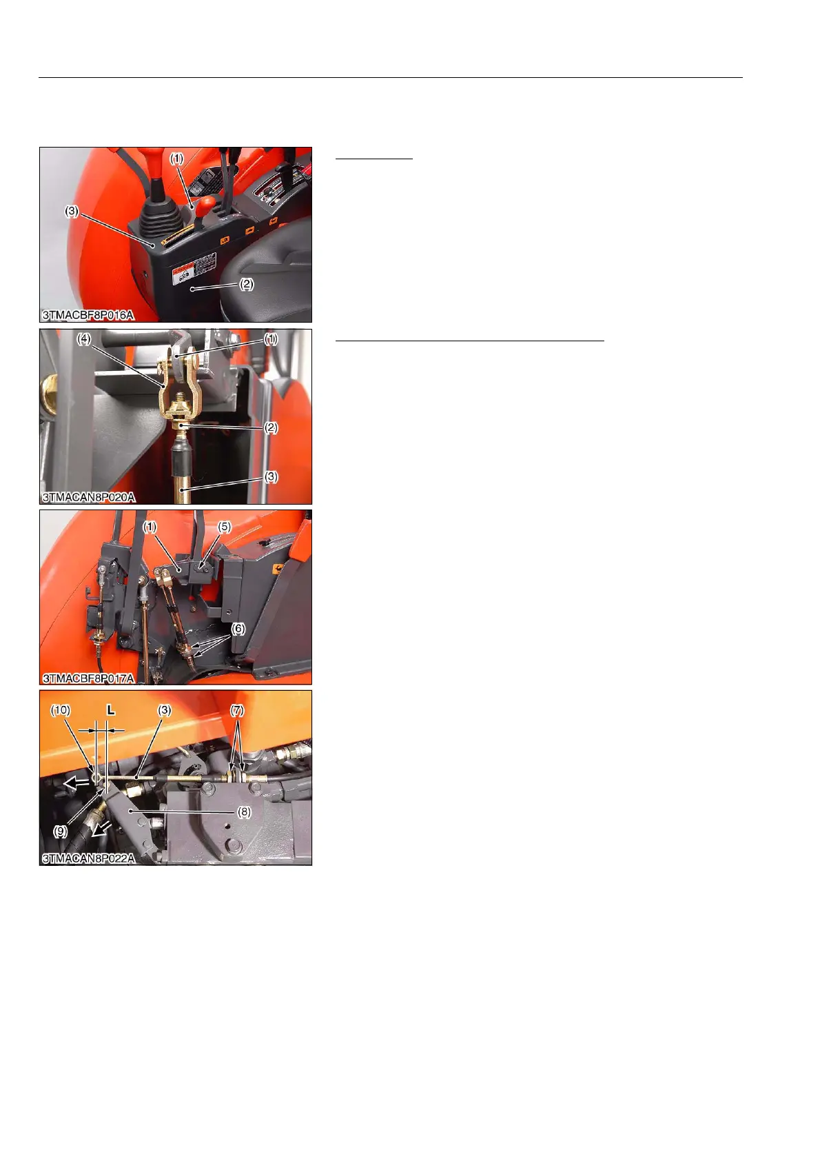
[4] AUXILIARY CONTROL VALVE LINKAGE
(1) ROPS Model
Preparation
1. Remove the hand accelerator lever grip (1).
2. Remove the shift lever cover 2 (3) and 1 (2).
9Y1210143HYS0014US0
Adjusting Wire of Auxiliary Control Valve
(Lever Side)
1. Screw in the wire (3) to the rod end (4) fully.
2. Shift the control lever (1) forward and fix the wire with lock nuts
(2) to contact the control lever (1) and stopper (5).
3. Fix the wire (3) with retaining nut (6) center of thread.
(Valve Side)
1. Pull the auxiliary valve lever (8) to a full engage position.
2. Pull out the wire (3) fully, and fix the wire with retaining nuts (7)
to be a length "L" between wire end (10) and valve lever pin (9)
as shown photo.
9Y1210143HYS0015US0
(1) Hand Accelerator Lever Grip
(2) Shift Lever Cover 1
(3) Shift Lever Cover 2
(1) Control Lever
(2) Lock Nut
(3) Wire
(4) Rod End
(5) Stopper
(6) Retaining Nut (Lever Side)
(7) Retaining Nut (Valve Side)
(8) Auxiliary Valve Lever
(9) Lever Pin
(10) Wire End
L: 0 to 3.0 mm (0 to 0.118 in.)