HYDRAULIC SYSTEM
M6040, M7040, WSM
8-M8
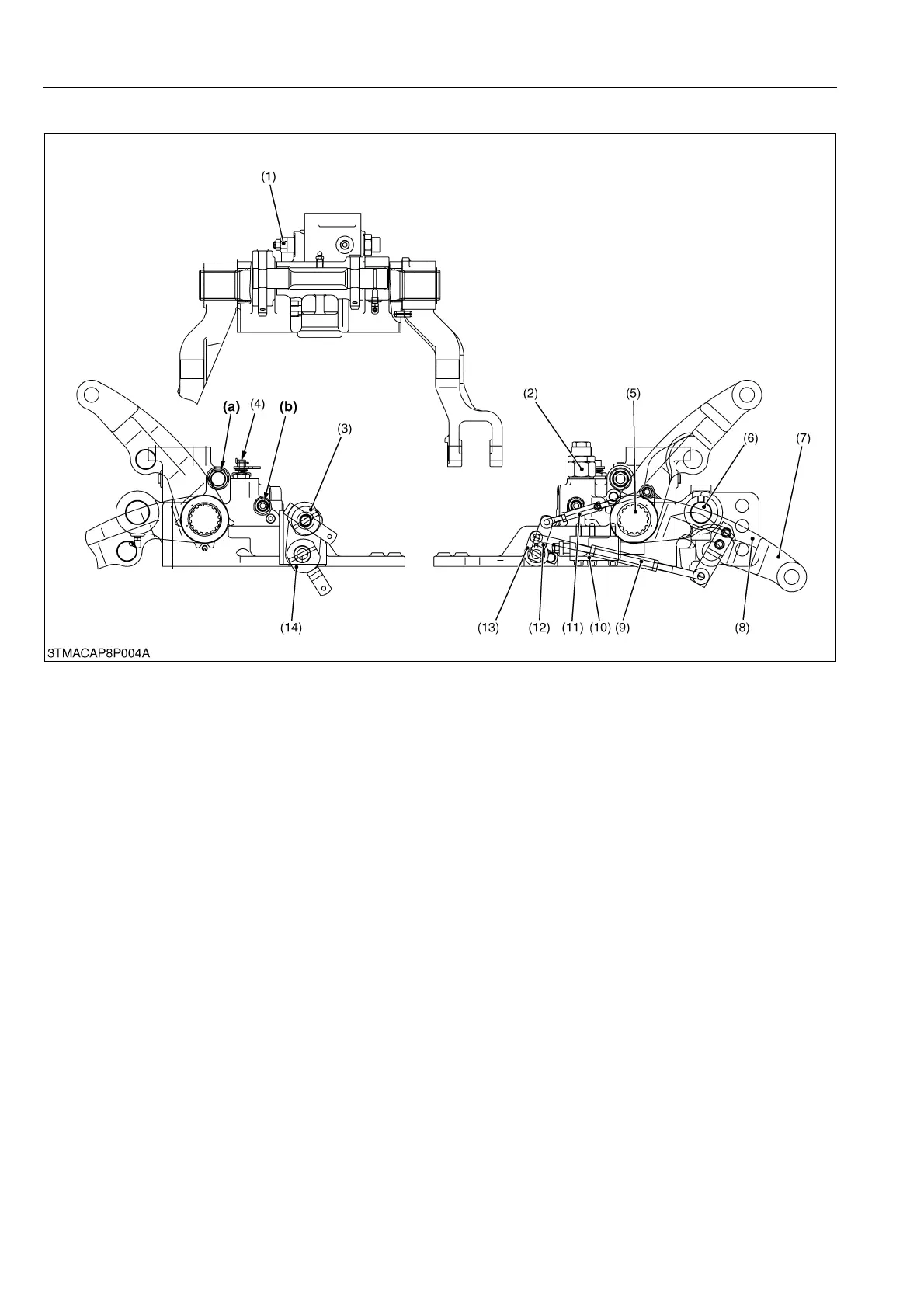
[3] HYDRAULIC BLOCK
The hydraulic block is equipped with cylinder safety valve (2), relief valve (1), lowering speed adjusting valve (4),
check valve, control valve (10), lift arm (7), lift arm shaft (5), torsion bar (6), position feedback rod (11) and draft
feedback rod (9) etc.
The hydraulic outlet port (b) is located in the hydraulic block to take power from the tractor to operate the hydraulic
cylinders of the three point linkage.
1. To operate the control valve, refer to "8. HYDRAULIC SYSTEM / (7) Position Control Valve - Type 7" in the
workshop manual of tractor mechanism (Code No. 9Y021-18200).
2. To operate the relief valve operation, refer to "8. HYDRAULIC SYSTEM / 4. RELIEF VALVE / [2] PILOT
OPERATED TYPE" in the workshop manual of tractor mechanism (Code No. 9Y021-18200).
3. To operate the cylinder safety valve (surge relief valve) operation, refer to "8. HYDRAULIC SYSTEM / 7.
CYLINDER SAFETY VALVE (SURGE RELIEF VALVE)" in the workshop manual of tractor mechanism (Code No.
9Y021-18200).
9Y1210143HYM0007US0
(1) Relief Valve
(2) Cylinder Safety Valve
(3) Draft Control Linkage
(4) Lowering Speed Adjusting
Valve
(5) Lift Arm Shaft
(6) Torsion Bar
(7) Lift Arm
(8) Top Link Bracket
(9) Draft Feedback Rod
(10) Control Valve
(11) Position Feedback Rod
(12) Position Feedback Link
(13) Draft Feedback Link
(14) Position Control Linkage
(a) To Implement Cylinder
(b) To or From Hydraulic
Cylinder