HYDRAULIC SYSTEM
M6040, M7040, WSM
8-S17
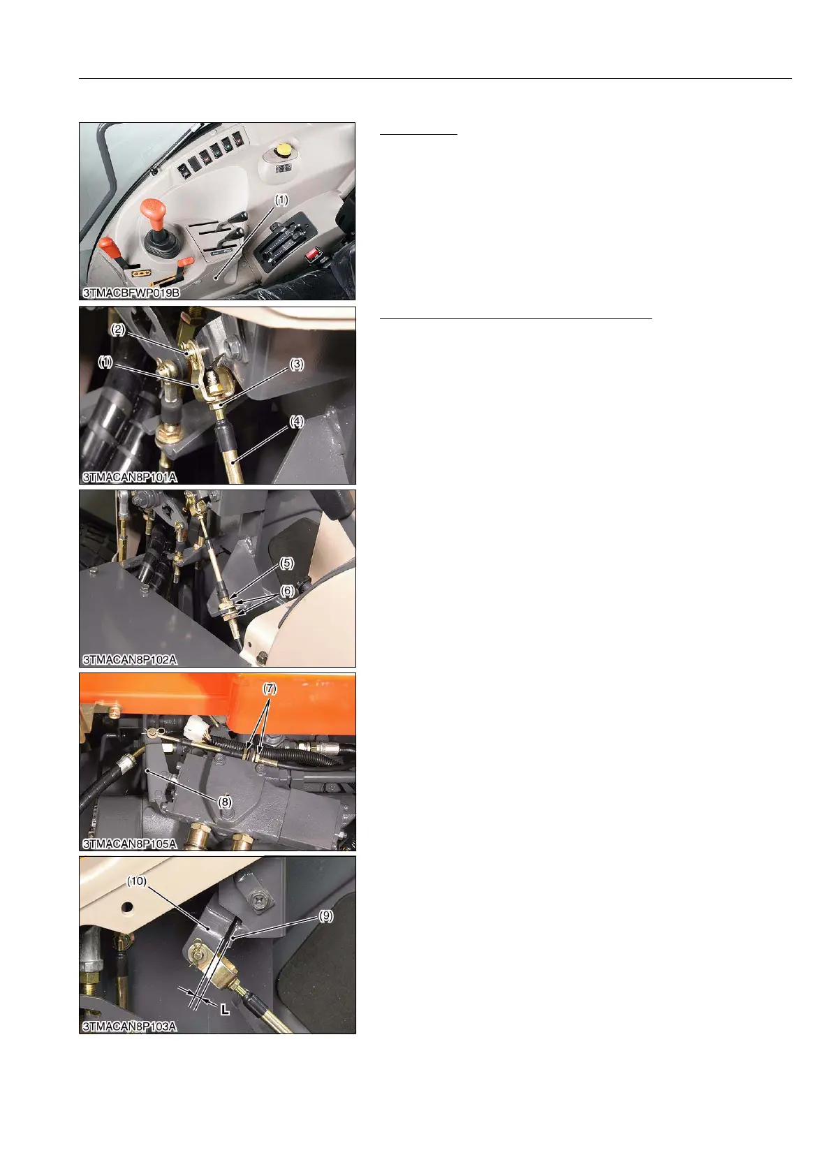
(2) CABIN Model
Preparation
1. Remove the inner cover R.H. 2 (1).
9Y1210143HYS0016US0
Adjusting Wire of Auxiliary Control Valve
(Lever Side)
1. Screw in the wire (4) to the rod end (1) fully.
2. Temporarily fix the wire (4) with retaining nuts (6) center of
thread (5).
(Valve Side)
1. Fix the wire end to the auxiliary valve lever (8).
2. Assemble the cable with retaining nut (7) to the left end side of
thread.
3. Adjust the retaining nut (6), so that the clearance "L" between
control lever (10) and to stopper plate (9) to be factory
specification when operate the control lever (10).
(When reassembling)
• Insert the pin (2) from the fender side.
9Y1210143HYS0017US0
(1) Inner Cover R.H. 2
(1) Rod End
(2) Pin
(3) Lock Nut
(4) Wire
(5) Thread
(6) Retaining Nut (Lever Side)
(7) Retaining Nut (Valve Side)
(8) Auxiliary Valve Lever
(9) Stopper Plate
(10) Control Lever
L: 1.0 mm (0.039 in.)