BRAKES
M6040, M7040, WSM
5-S15
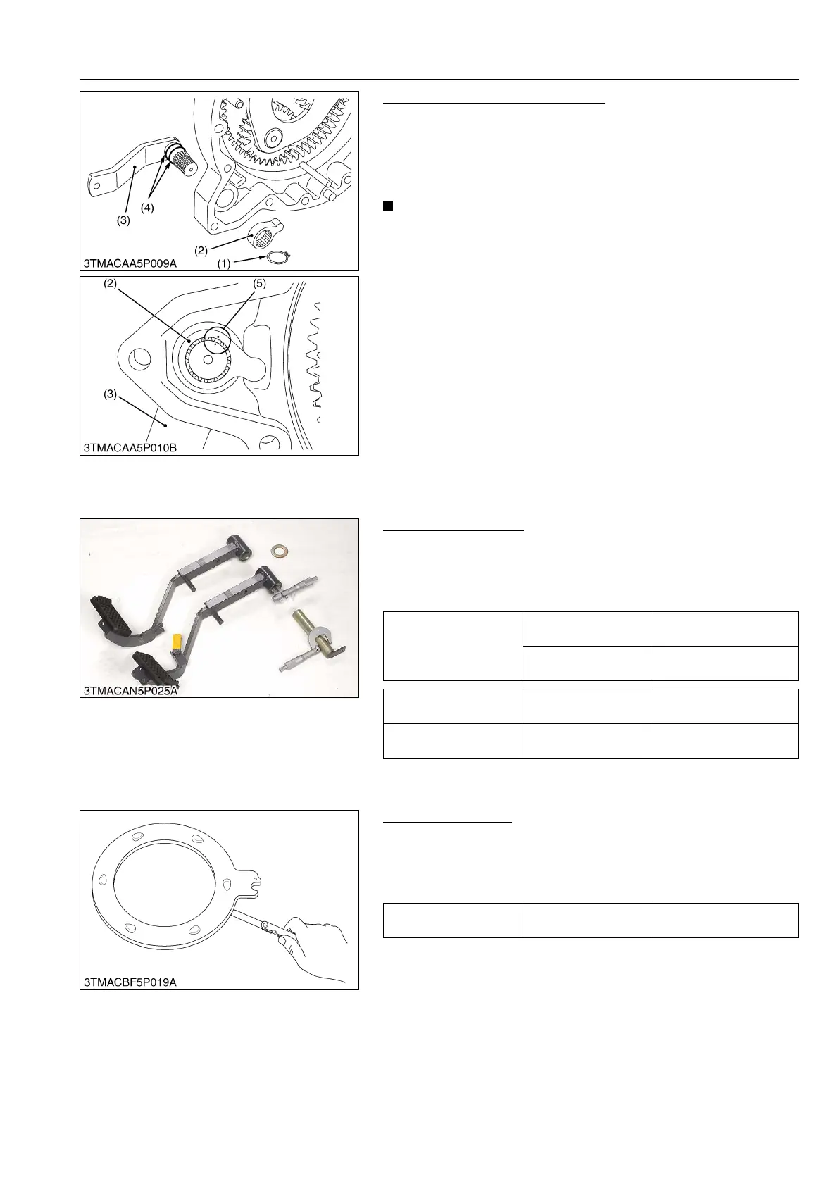
Brake Cam and Brake Cam Lever
1. Remove the external circlip (1).
2. Remove the brake cam (2) and brake cam lever (3).
(When reassembling)
• Apply grease to the O-ring (4) and take care not to damage the
O-ring.
• Install the brake cam (2) to brake cam lever, aligning the
marks on them.
9Y1210143BRS0026US0
[3] SERVICING
(1) Brake Pedal
Brake Pedal Bushing
1. Measure the brake pedal bushing I.D. with inside micrometer.
2. Measure the pedal shaft O.D. with outside micrometer and
calculate the clearance.
3. If the clearance exceeds the allowable limit, replace it.
9Y1210143BRS0027US0
(2) Travelling Brake
Cam Plate Flatness
1. Place the cam plate on the surface plate.
2. Measure the flatness of cam plate with a feeler gauge at four
points on a diagonal line.
3. If the measurement exceeds the allowable limit, replace it.
9Y1210143BRS0028US0
(1) External Circlip
(2) Brake Cam
(3) Brake Cam Lever
(4) O-ring
(5) Alignment Mark
Clearance between
brake pedal bushing and
pedal shaft
Factory specification
0.03 to 0.246 mm
0.0012 to 0.0097 in.
Allowable limit
0.5 mm
0.0197 in.
Brake pedal bushing I.D. Factory specification
25.030 to 25.146 mm
0.9854 to 0.9900 in.
Pedal shaft O.D. Factory specification
24.9 to 25.0 mm
0.9803 to 0.9843 in.
Cam plate flatness Allowable limit
0.3 mm
0.012 in.