6-29
Throttle body and throttle link adjustment
TIP:
• To increase the output voltage, turn the
TPS “2” in direction “a”.
• To decrease the output voltage, turn the
TPS “2” in direction “b”.
14. Tighten the TPS screws.
15. Start the engine and move the shift lever
from the N position to the F position, and
then return it to the N position.
16. Check the engine speed.
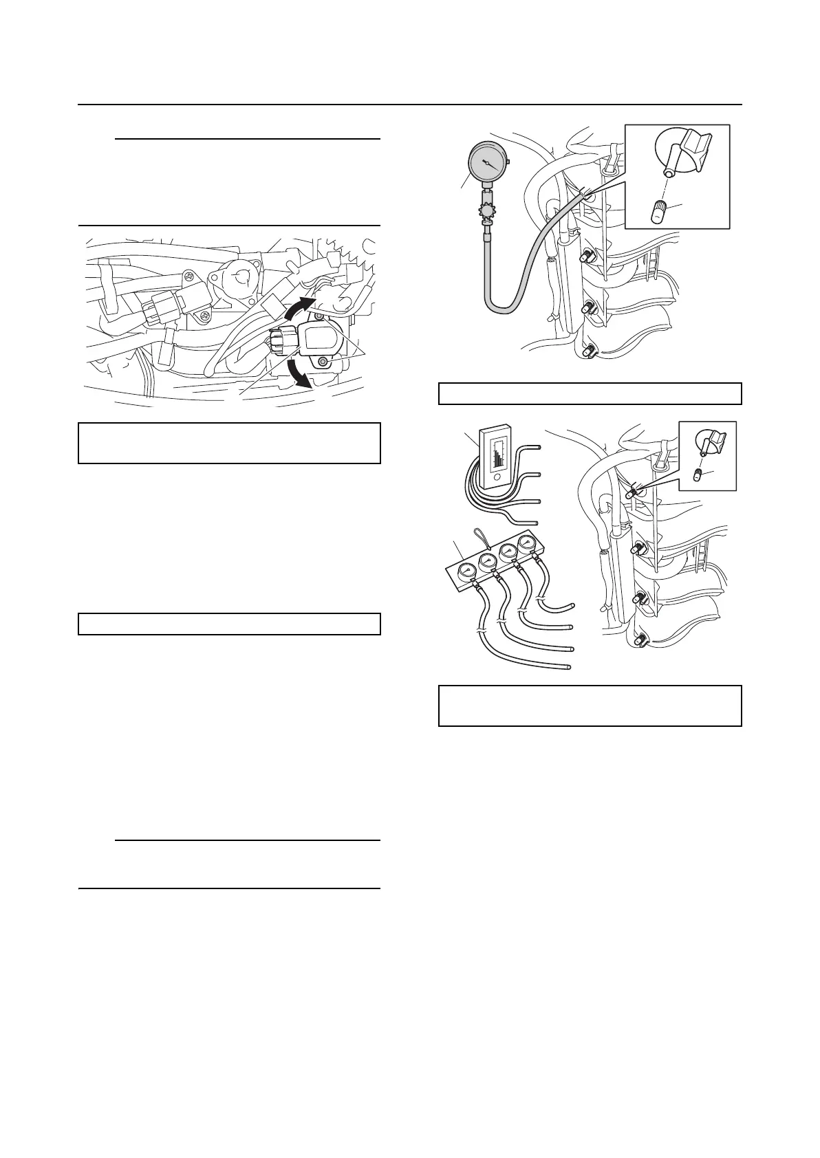
Checking the synchronization of the
throttle valve
Do not adjust the throttle valves when they
are operating properly.
1. Remove the caps “1”, and then connect
the special service tool “2” to the intake
manifold.
TIP:
Use a commercially available vacuum gauge
“3” or “4” with 4 adapters.
2. Start the engine and warm it up for 5 min-
utes.
3. Check the vacuum pressure of all cylin-
ders.
4. Check that the difference of the vacuum
pressure between cylinders #1 or #2 and
#3 or #4 is less than 2.0 kPa
(15.0 mmHg). If the difference is more
than 2.0 kPa (15.0 mmHg), adjust the
throttle valve reference opening angle.
See “Adjusting the throttle valve refer-
ence opening angle” (6-27).
TPS output voltage:
0.70–0.72 V
Engine idle speed: 650–750 r/min
1
b
a
2
Vacuum gauge “2”: 90890-03159
Vacuum gauge “3” and “4”:
(commercially available)
1
2
1
3
4