7-2
Power unit (check and adjustment)
4. Remove the canister. See “Removing the
canister” (6-18).
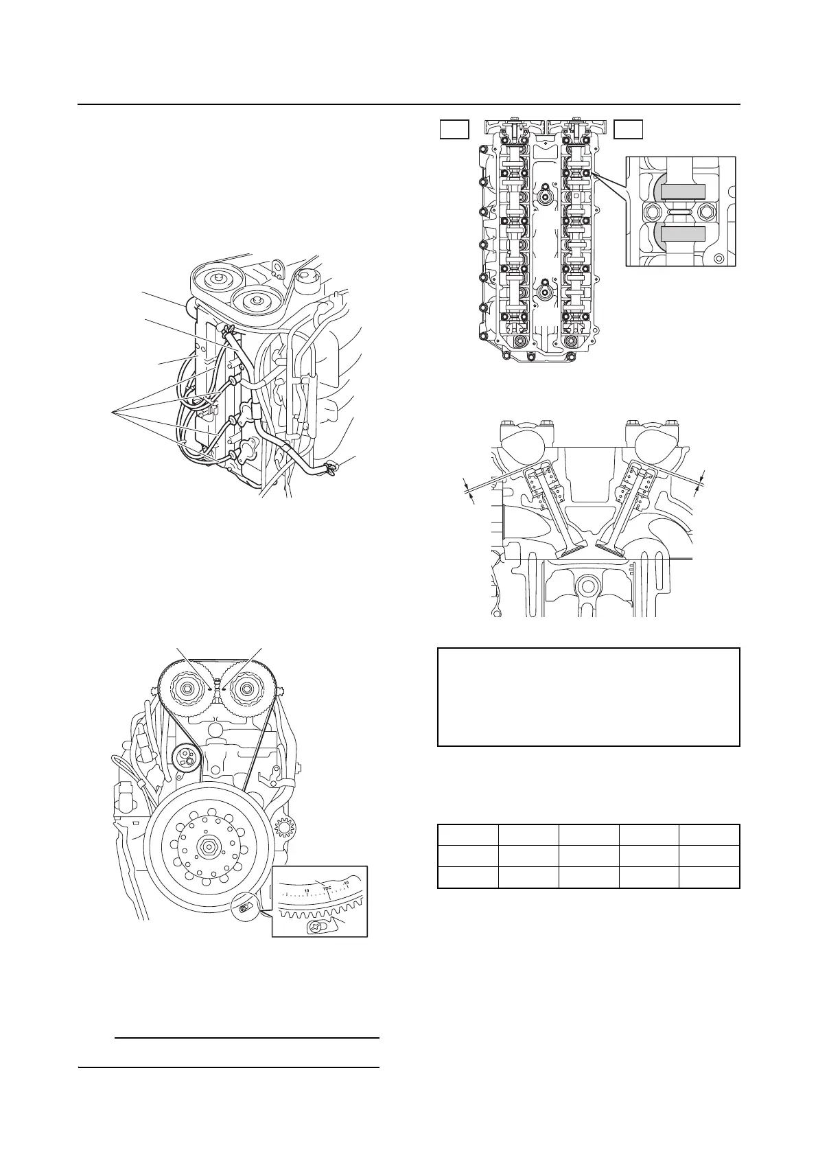
5. Disconnect the spark plug wires “1”, and
then remove the blowby hoses “2” and
“3”, all of the spark plugs, and cylinder
head cover “4”.
6. Turn the flywheel magnet clockwise to
align the “TDC” mark “a” on the flywheel
magnet with the pointer “b”. Check that
the “I” marks “c” and “d” on the driven
sprockets are aligned.
7. Measure the valve clearances “a” and “b”
according to steps 8–10.
TIP:
Write down the measurement data.
8. Measure the intake and exhaust valve
clearances of the specified cylinders.
Adjust if out of specification.
—: Not applicable
✔: Specified cylinder
9. Turn the flywheel magnet clockwise 360°
to align the “TDC” mark on the flywheel
magnet with the pointer.
1
2
3
4
a
b
c
d
Valve clearance:
Intake “a”:
0.17–0.24 mm (0.0067–0.0094 in)
Exhaust “b”:
0.31–0.38 mm (0.0122–0.0150 in)
#1 #2 #3 #4
IN ✔✔——
EX ✔ — ✔ —
#1
#2
#3
#4
EX IN
a
b