3-8
Outboard motor mounting
0
1
2
3
4
5
6
7
8
9
10
A
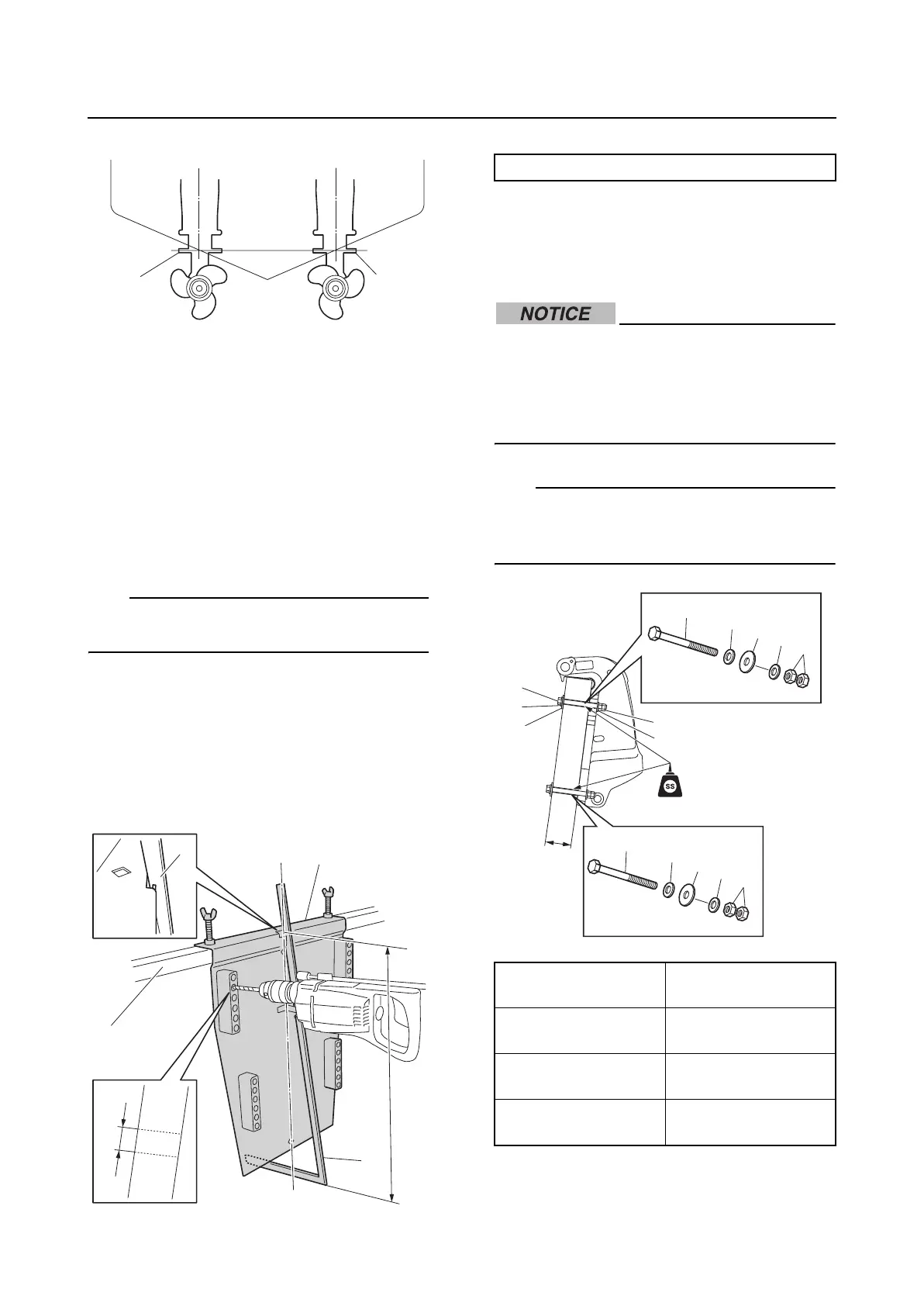
A. Single outboard motor
B. Twin outboard motor
3. Install the special service tool “1”.
4. Adjust the height of the scale “2” to the
transom height (H), and place it on the
special service tool “1”. Secure the spe-
cial service tool “1” to the boat transom
using screws or vises.
TIP:
For the transom height (H), see “External
dimensions” (3-5).
5. When the outboard motor mounting posi-
tion has been determined, mark the best
suited 4 symmetrical mounting holes on
the boat transom “3”. Drill the mounting
holes perpendicular to the surface of the
boat transom using a 13.0 mm (0.5 in)
“a” drill bit.
C/L: Centerline of the transom
6. Apply sealant to the mounting holes, and
then secure the outboard motor using the
included mounting bolts “1”, small wash-
ers “2”, large washers “3”, and nuts “4”.
Make sure that there is no clearance
between the surfaces of the boat transom
and the clamp brackets. Otherwise, the
clamp brackets or boat transom may be
damaged.
TIP:
The second hole from the top of each clamp
bracket is recommended for the upper
mounting bolt.
1
1
B
H
C/L
2
a
1
2
3
Drilling plate “1”: 90890-06783
Boat transom
thickness (D)
Mounting bolt
55–65 mm
(2.17–2.56 in)
M12 × 115 mm
(4.53 in)
65–75 mm
(2.56–2.95 in)
M12 × 130 mm
(5.12 in)
75–95 mm
(2.95–3.74 in)
M12 × 150 mm
(5.91 in)
4
1
2
2
3
1
2
2
3
4
D
4
1
2
2
3