Chapter 10 Distance to Fault Operation
About the distance to fault mode
164 9102 Handheld Spectrum Analyzer Software version 5.31
About the distance to fault mode
The distance-to-fault measurement is essential for antenna installa-
tions. It focuses on the cable measuring the reflection arising along it
in order to detect and locate weak connectors, cable kinks, water
ingress and other cable-related problems. This measurement is also
called structural return loss and it displays reflection arising at a certain
cable position precisely in the location domain. Thereby cable prob-
lems can be easily identified. The 9102 supports a detailed analysis of
the antenna feeder cable with a total length of up to 2000 m. The high
501 points measurement resolution ensures quick and efficient trou-
bleshooting by detecting even small reflections which result in a
displayed distance to fault.
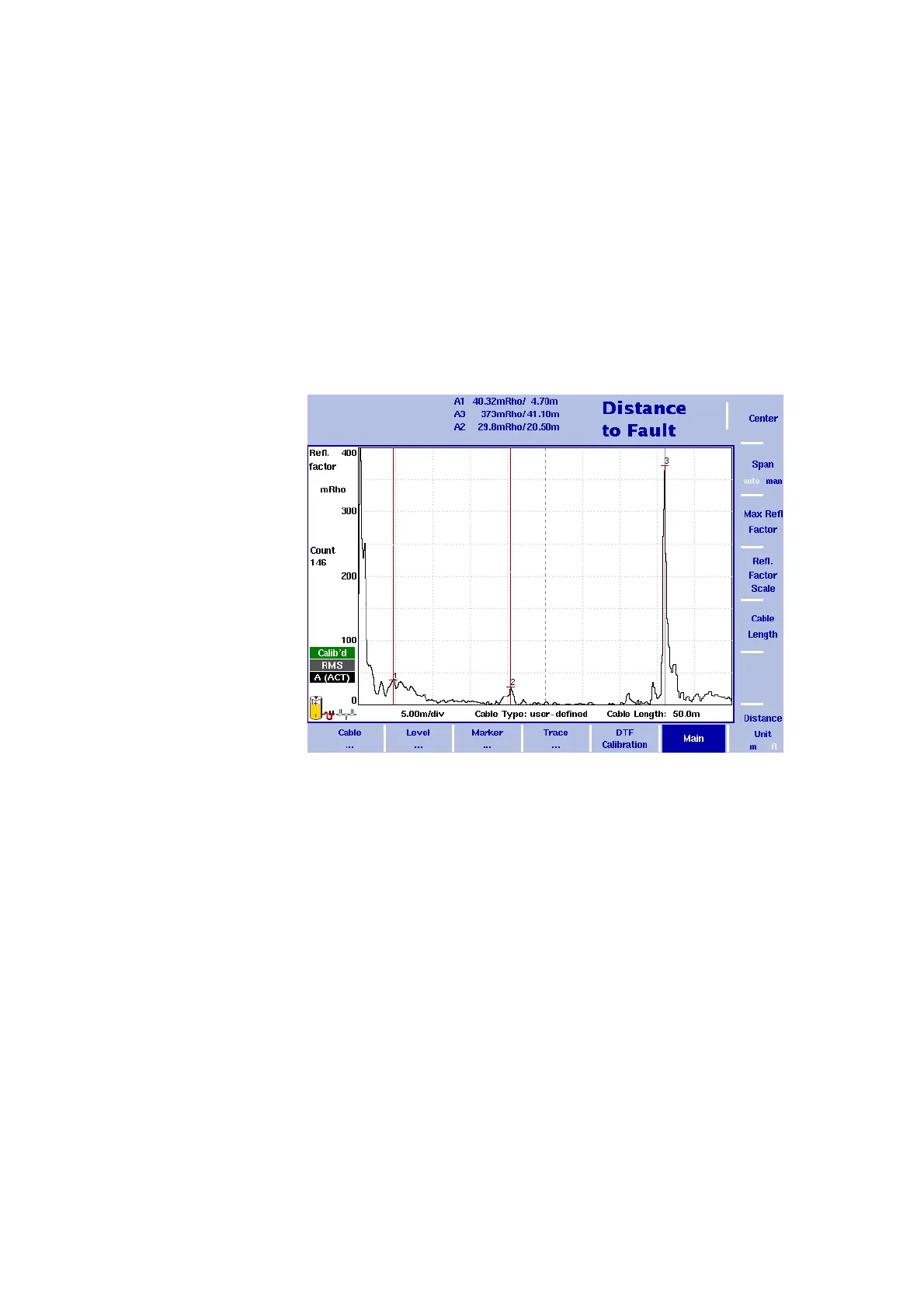
Figure 47 shows an example of a distance-to-fault results display. As in
the other measurement modes you can use markers to label all peaks.
In the distance to fault mode the markers appear in line style. For a
detailed application example for the distance to fault measurement
mode refer to the applications guide contained on the documentation
CD delivered with your instrument.
Figure 47 Example of a distance-to-fault measurement


 To Next Page