Chapter 15 9100 Data Exchange Software
Defining and loading external coupling parameters
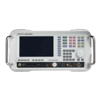
244 9102 Handheld Spectrum Analyzer Software version 5.31
Defining the external
coupling factor
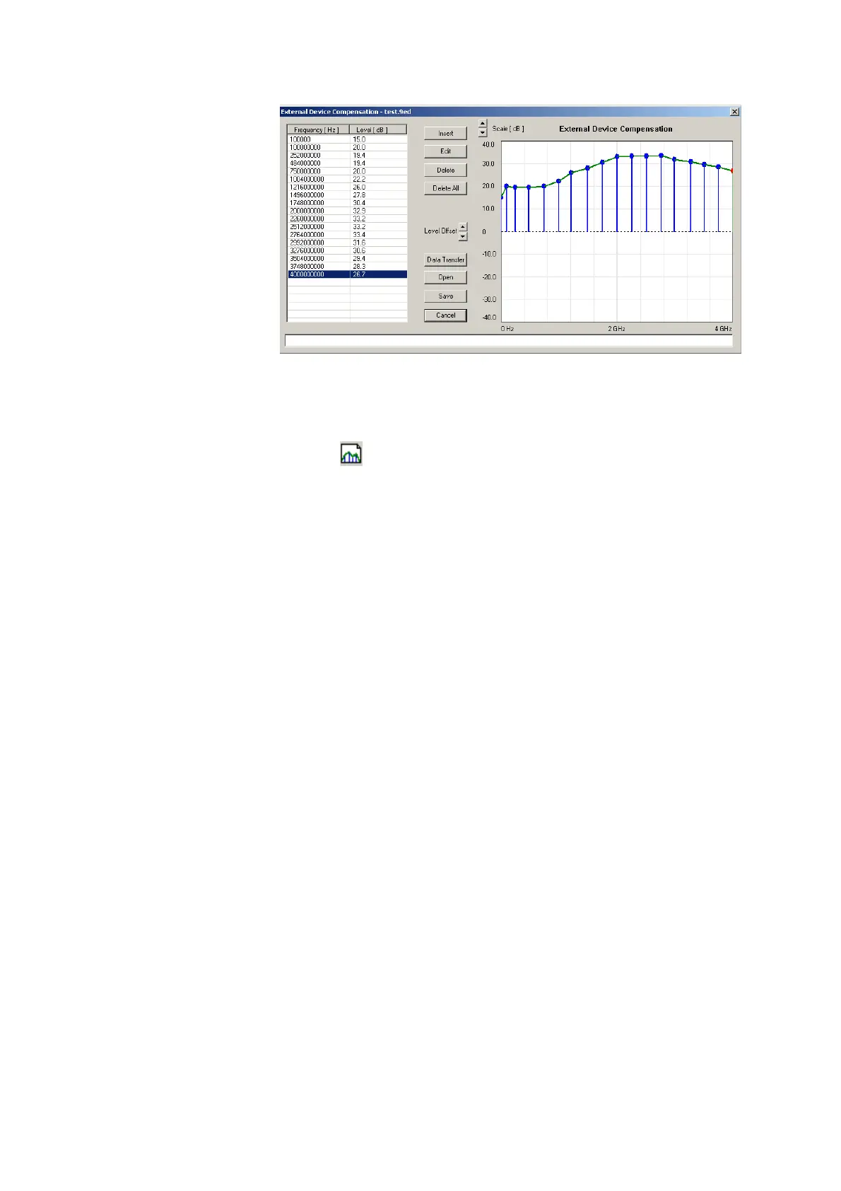
1 Open the External Device Compensation menu by selecting Tools >
External Device Editor...
or by pressing Alt+E or by clicking on the
icon:
2 To enter an interpolation point, select
Insert.
A dialog box appears, allowing you to enter frequency and level.
3 Enter the frequency, select a unit (from hertz to gigahertz) and
enter the coupling factor (in dB). Positive factors indicate signal
attenuation, negative factors indicate gain in the signal line.
4 Close the box by pressing
OK and repeat the last two steps with as
many interpolation points as available.
The frequency-dependent compensation curve appears on the
right-hand side as values are entered.
5 If you want to change a factor, either select a line from the table on
the left-hand side and click on
Edit to change the values numeri-
cally, or point with the mouse to an interpolation point in the graph
on the right and drag it to a new position.
6 To move the whole interpolation curve up or down in steps of 1 dB,
click on the
Level Offset arrow buttons.
7 When completed, save the device compensation values in a file on
the PC: Click on
Save, enter a file name and confirm by clicking on
Save.
8Press
Cancel to close the External Device Compensation window.
Loading an external
coupling loss file to the
9102
One or more files with external coupling loss data can be transferred
to the 9102 and reside in the internal memory of the 9102. They will
not be taken into account until they are activated (see “Compensating
gains and losses”).
1 Select
Instrument > Data Transfer (Ctrl-D), or in the External Device
Compensation menu, select
Data Transfer.
The Data Transfer menu opens.


 To Next Page