Chapter 15 9100 Data Exchange Software
Managing cable factors for EMF measurements
250 9102 Handheld Spectrum Analyzer Software version 5.31
Managing cable factors for EMF measurements
If you are using an extension cable for your EMF measurement setup,
for example in order to mount an antenna on a tripod and turning
device, cable attenuation has to be taken into account by using the
appropriate cable correction factors on the 9102. You maintain and
edit these cable factors within the 9100 Data Exchange software. In
order to employ them during EMF measurements on the 9102 you can
then transfer them to your instrument.
For further details on the usage of cable factors during EMF measure-
ments refer to Chapter 12 “EMF (EMI) Operation”.
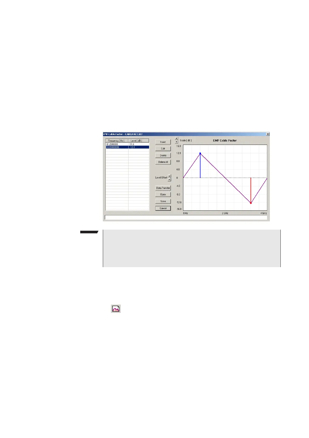
Defining a cable factor 1 Open the EMF Cable Factor menu by selecting Tools > EMF Cable
Factor Editor...
or by pressing Alt+F or by clicking on the icon in the
menu bar:
.
2 To enter an interpolation point, select
Insert.
A dialog box appears, allowing you to enter frequency and level.
3 Enter the frequency, select a unit (from hertz to gigahertz) and
enter the coupling factor (in dB). Positive factors indicate signal
attenuation, negative factors indicate gain in the signal line.
4 Close the box by pressing
OK and repeat the last two steps with as
many interpolation points as available.
The frequency-dependent compensation curve appears on the
right-hand side as values are entered.
NOTE
The functionality described in the following sections is specifically
dedicated to the usage of the 9131 EMF Measurement Option. If this
option is not installed and activated on your 9102 this functionality is
of no practical use.


 To Next Page