Chapter 2 General Operation
Connecting the 9102 Handheld Spectrum Analyzer
14 9102 Handheld Spectrum Analyzer Software version 5.31
Connecting the 9102 Handheld Spectrum Analyzer
DC IN connector The 9102 can be operated either from the internal battery or from an
external DC source such as the power supply which is delivered with
the 9102. In addition, the battery is loaded when an external DC source
is connected. See the specifications in your getting started manual for
details of the required DC source. Here you will also find detailed infor-
mation on installing and maintaining the battery.
Apply the source to the DC
IN connector at the top of the 9102.
RF
IN connector RF in is a 50 N-type connector (female).
If you have a 50 shielded RF cable with an N-type connector (male)
to connect to the device under test, simply screw the connector tightly
to the 9102.
If you have a 50 shielded RF cable with a BNC connector (male), use
an N to BNC adapter to connect the cable to the 9102. Aeroflex offers
an appropriate adapter; see section “Options and accessories” on
page 5.
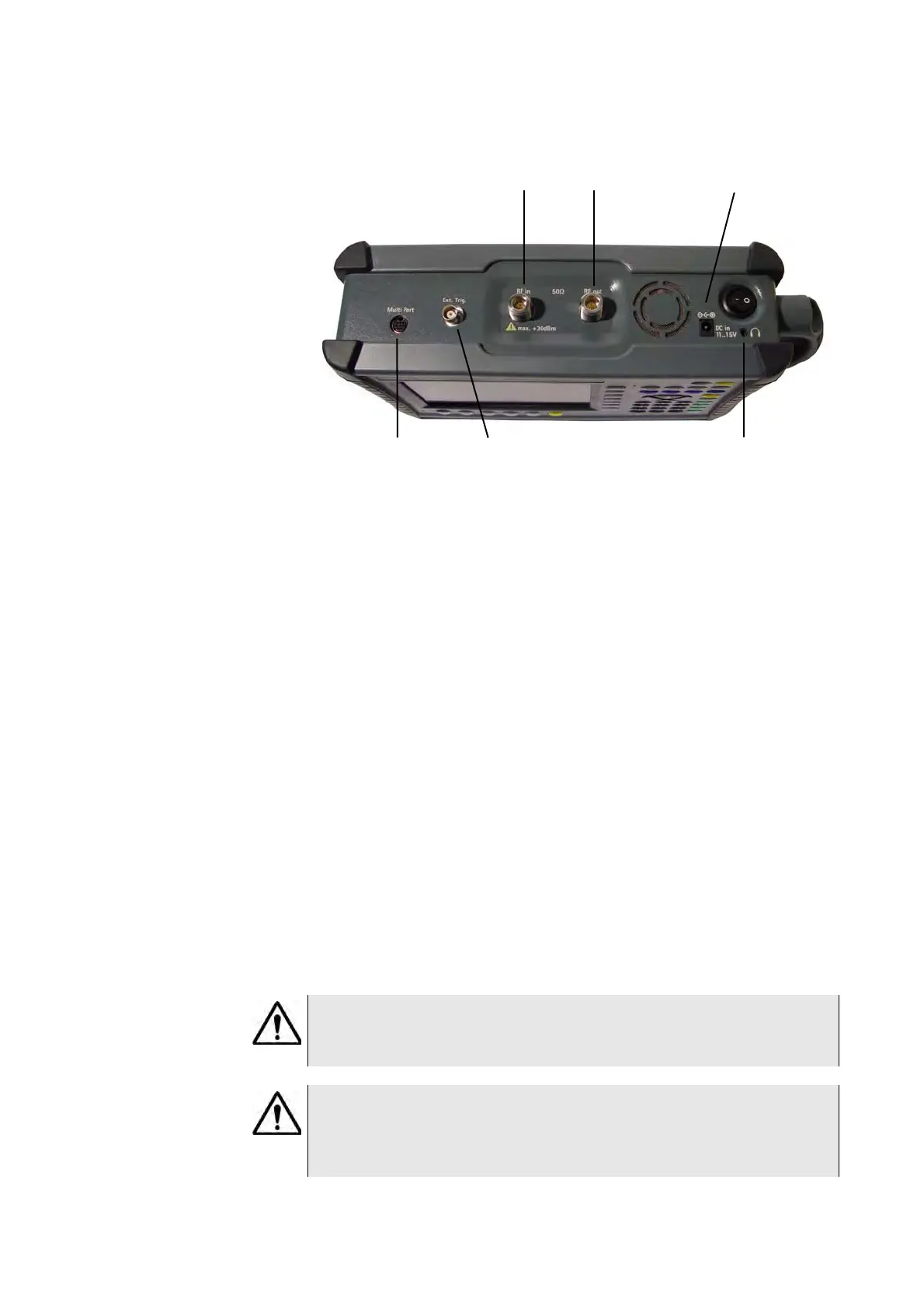
Figure 1 9102 connectors on the top of the instrument
DC in
RF in
Multi Port Ext. Ref. in/Ext. Trigger
Headphone jack
RF out
WARNING
The maximum allowable input power level at the RF
IN connector is
30 dBm (1 W). Higher levels at this port can damage the instrument!
CAUTION
Only use a 50 N-type connector to connect to the RF
IN port of
the 9102. Use of any other connector may result in damage of the
instrument.