Chapter 2 General Operation
Using the front panel
9102 Handheld Spectrum Analyzer Software version 5.31
21
Trace finder
If more than 90 percent of a results trace is not shown onscreen
because it is above or below screen boundaries, a trace finder icon
consisting of an up or down arrow and the word “Trace“ shows where
the trace can be found. The trace finder icon is positioned in the middle
of the results display. By modifying the reference level accordingly you
can bring the trace back into view.
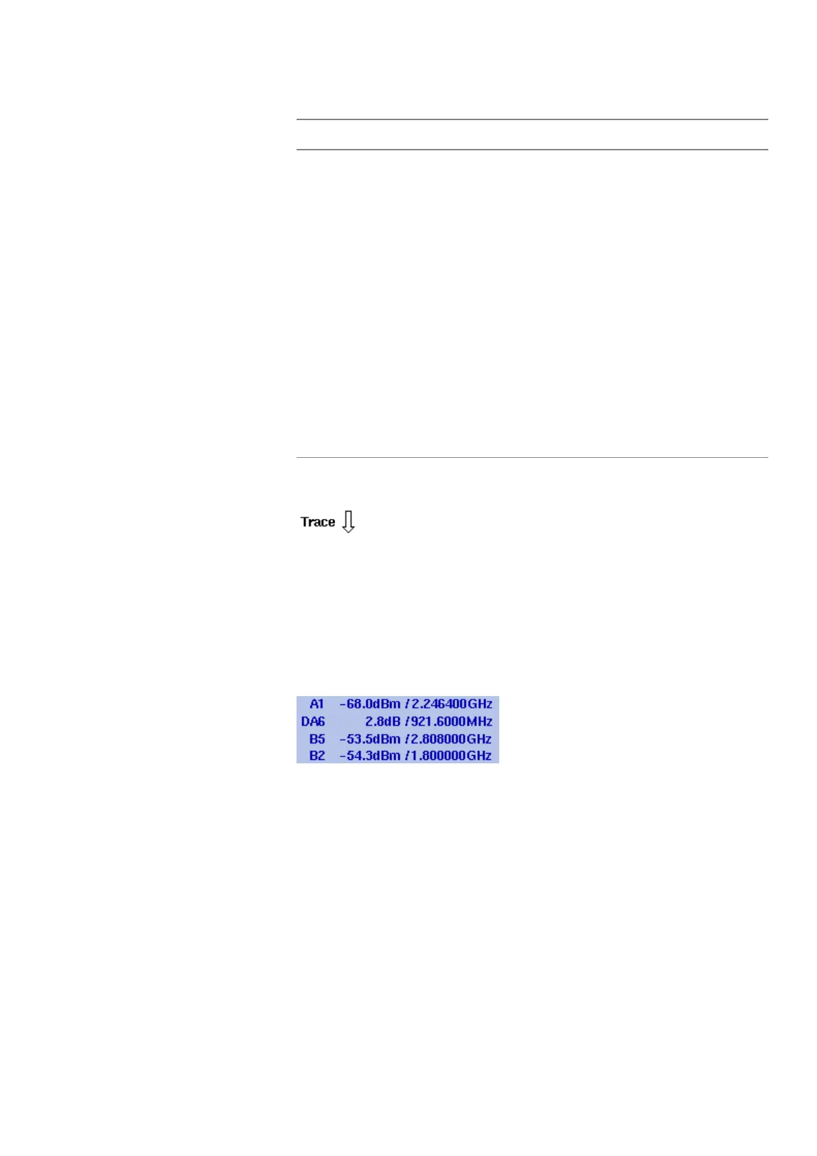
Marker field
If any of the markers is active, the marker field is displayed, showing the
measurement values at the marker positions. Up to four markers are
displayed with their level and frequency values. If you use four markers
and activate a fifth (up to six markers are available) one marker value
will be hidden and the new one will be displayed instead. By pressing
the relevant marker softkey you can display the hidden marker value
again. A marker can be switched from absolute to relative values. The
values are then shown relative to those of marker 1 (e.g. A1).
Pos./Neg.
Pos. Peak
Neg.
Peak
Sample
RMS
Shows the current detector setting. The detector can
be changed as explained in section “Selecting the
detection method” on page 71. The RMS detector is
available if the 9132 RMS Detector Option is installed
and activated on your 9102.
A/B
(ACT)
A/B
(HLD)
A/B
(MAX)
A/B
(MIN)
A/B
(AVG)
Shows the currently selected trace mode for the
respective trace. The background color of the text
coincides with the color of the graph. For more infor-
mation on trace modes, see section “Selecting the
trace mode” on page 68.
Table 7 Texts on the left-hand side
Text Meaning