Chapter 15 9100 Data Exchange Software
Defining and loading limit templates
240 9102 Handheld Spectrum Analyzer Software version 5.31
The limits are expressed relative to the grid on the 9102 display, not as
absolute values in terms of frequency (or time) and power. This way,
you can apply the same template to different power levels and frequen-
cies provided that the scales are as intended.
Defining limits Limits can be defined as a template with an upper and and a lower limit
curve. Each curve consists of a number of straight lines between
points. The Limits menu of the 9100 Data Exchange Software allows
you to enter and display such lines.
The limits are expressed relative to the grid on the screen, with eight
horizontal and ten vertical lines. The coordinates of each point (in x/y
coordinates) correspond to these lines.
To define a new template, proceed as follows:
1 In the 9100 Data Exchange Software, select
Tools > Limit Editor...
or click on the icon in the menu bar: .
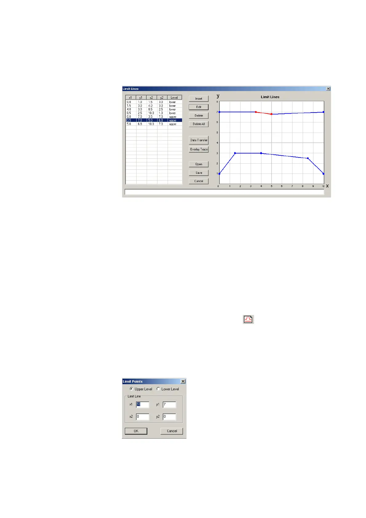
The Limit Lines window is displayed, with a limits coordinates table
on the left and the limit lines on the right-hand side.
2 To enter a new limit line, press
Insert.
A window appears, allowing you to enter the x/y coordinates for
two points.
3 Select whether you wish to define an upper or lower limit by
selecting one of the
Upper Level and Lower Level radio buttons.
4 Enter the coordinates for the first point of the limit line (x1, y1).