TABLE F - INSTRUMENT HOLDER ARCH
BRACE AND FRONT PART
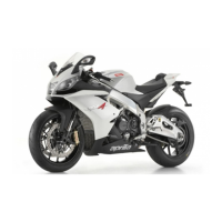
Pass all the cable harnesses arriving from the right
semi-handlebar (right handlebar control + front
stop switch) and from the left semi-handlebar (left
handlebar control + key switch) inside of the right
arch brace, as shown in the figure; also pass the
cable with the clutch connector on the vehicle ca-
ble harness together with the left switch cable
harness.
Use a clamp (32), as shown in figure, to hold the
various cable harnesses inside the arch brace.
32. Clamp
TABLE G - INSTRUMENT HOLDER ARCH
BRACE AND FRONT PART
The left arch brace can now be fit.
After fitting the left arch brace, the clamp used for
holding the cable harnesses inside the arch brace
itself must be cut and removed.
33. Left turn indicator connector (cable colours:
light blue and blue)
34. Right turn indicator connector (cable colours:
red and blue)
35. Insert the connectors into their seats on the
arch brace
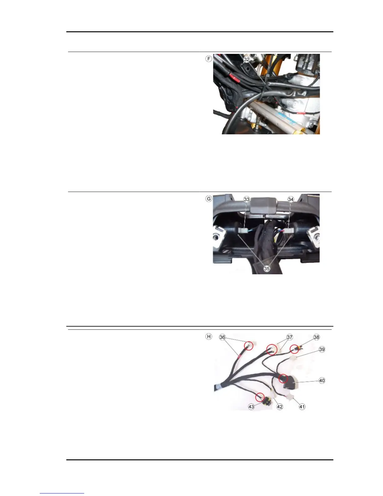
TABLE H - INSTRUMENT HOLDER ARCH
BRACE AND FRONT PART
36. Key switch connector (cable harness with red
taping)
37. Left handlebar control connectors
38. Antenna connector
39. Left turn indicator connector (cable colours:
light blue and blue)
40. Instrument panel connector
41. Right turn indicator connector (cable colours:
red and blue)
RSV4 R Electrical system
ELE SYS - 103
 Loading...