3. Physical installation
Scheimpflug adjustment points
4
1
2
3
d
D
c
C
A
a
B
b
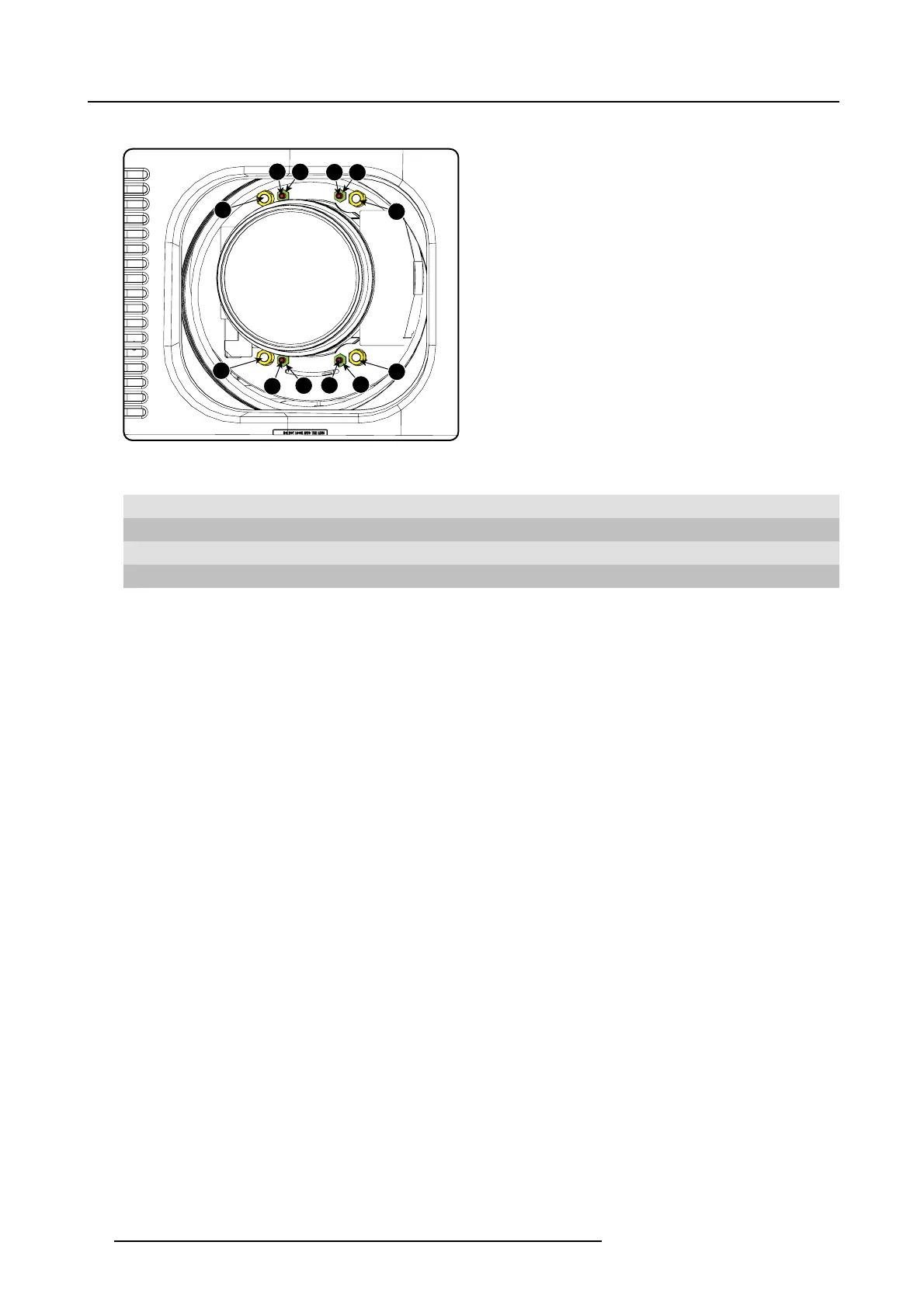
Image 3-29
Scheimpflug adjustments
Indication on drawing Function
4 Locking nut
1, 2 and 3 Scheimpflug adjustment nuts
A, B, C and D Set screws
a, b, c and d lock nuts
1, 2 and 3 are adjustment points.
4 is a locking point and NOT used during Scheimpflug adjustment.
Necessary tools
• Allenkey3mm
• Nut driver 13 mm
• Nut driver 10 mm
How to adjust
1. Project a green focus pattern. (image 3-30)
2. Loosen the lock nuts (a, b, c and d). See image 3-29.
3. Loosen the 4 set screws (A, B, C and D) by 1 cm. See image 3-29.
4. Fully loosen lock nut 4. See image 3-29.
5. Optimize the focus of the projected image as follows:
a) Place the zoom lens in TELE position (smallest projected image) and adjust the focus using the lens focus barrel or motorized
focus control.
b) Place the zoom lens in WIDE position (largest projected image) and adjust the focus by turning equally on nut 1, 2 and 3.
c) Repeat steps “a” and “b” until the projected image is as sharp as possible. (image 3-31)
6. Sharpen bottom left corner of the screen by adjusting nut 1. (image 3-32)
7. Sharpen bottom right corner of the screen by adjusting nut 2. (image 3-33)
8. Sharpen top right corner of the screen by adjusting nut 3 (image 3-34)
9. Repeat from step 6 until the projected focus pattern is as sharp as possible in the center, left, right, top and bottom of the screen.
30
R5905158 HDF W SERIES 10/07/2012

 Loading...


