3. Physical installation
How to connect your projector with the local power net ?
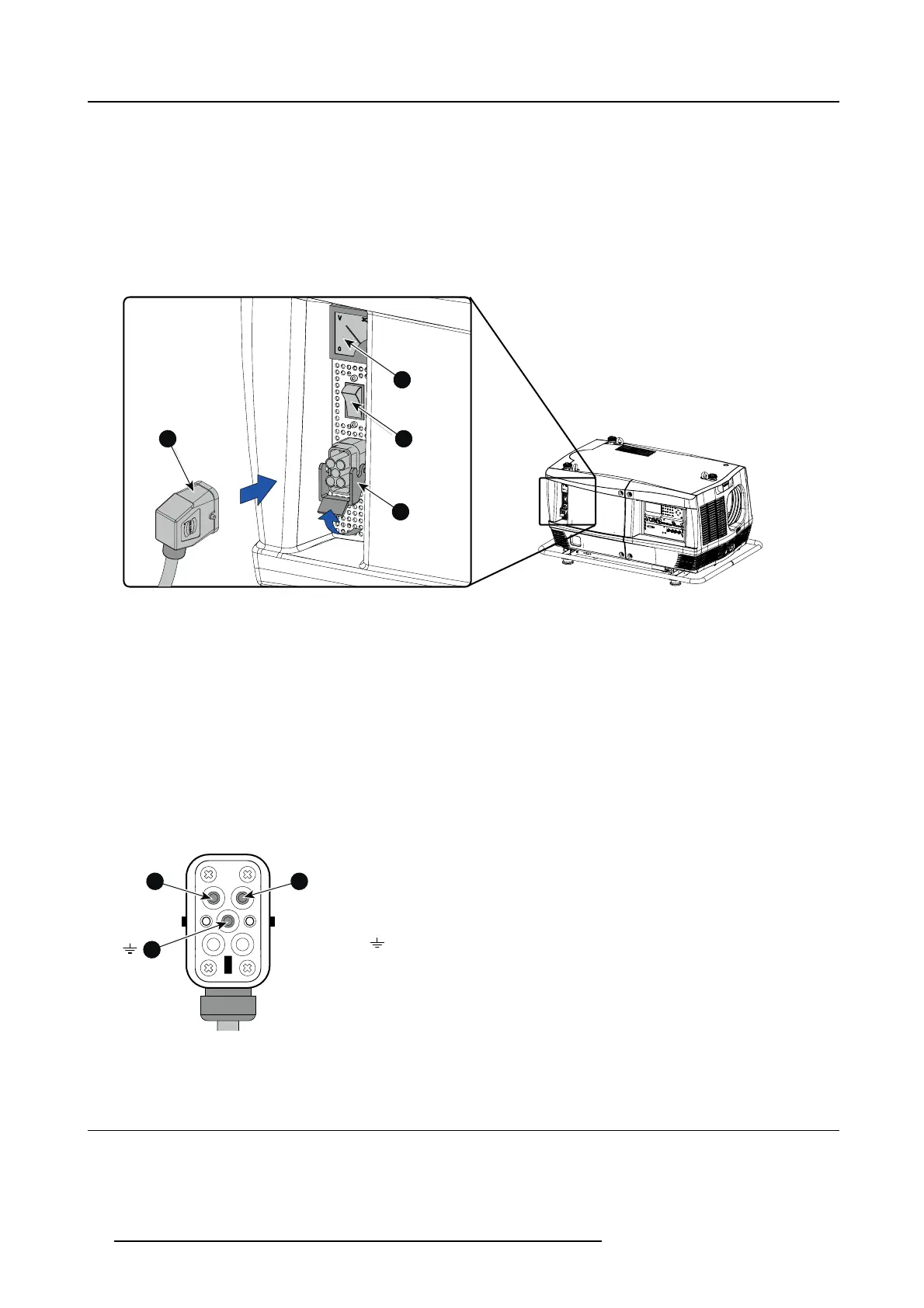
1. Ensure that the power switch (S) stands in the “0” (OFF) position.
2. Connect the power cord (P) with the power input socket of the projector as illustrated below.
3. Secure the power plug by locking the plug holder clamp (H).
4. Connect the other end of the power cord with the local power net.
Caution: E nsure that the power net meets the power requirements of the projector.
The voltmeter (M) will immediately indicate the value of the mains voltage as soon as the projector is connected with the power
net. (image 3-36)
1
2
M
S
H
P
P
M
S
H
Image 3-36
Power connection
Fuses
The projector is protected with an automatic circuit breaker of 35 A which is built in into the power switch.
Volt meter
After starting up the projector (lamp ignition) check if the value indicated by the volt meter is still within the specified power range of
the projector. Note that in case the power net drops significantly during start up, the lamp will fail the ignite. If this is the case, take
the necessary measures to reinforce the power net to the projector before starting up the projector again.
Volt meter is protected with a Miniature Fuse, 5 x 20 mm, T 1AH, 250 VAC, UL: 115 V - 300 VDC.
Spare power plug
The projector is delivered with a spare power plug. This spare power plug is attached behind the nameplate of the projector. Remove
the cover of the lamp first to access this spare power
plug. Note that only qualified technical personnel may install a new power plug.
43
21
HAN Q4/2 +
LN
PE
Image 3-37
Pin configuration power plug HAN Q4/2 + PE.
3.4 Suspension of the HDF W series proj
ector with rigging clamps
Rigging points and rigging clam
ps
The carrying handle, at the bottom side of the projector, is provided with eight slots. Four slots are longitudinally (A) oriented and
four slots are transversely (B) oriented. Each slot contains a rigging point of which the position in the slot can be adjusted depending
34
R5905158 HDF W SERIES 10/07/2012

 Loading...


