A53 Z0 9 0020 L En Technical documentation
Select the first column (A) with saved values.
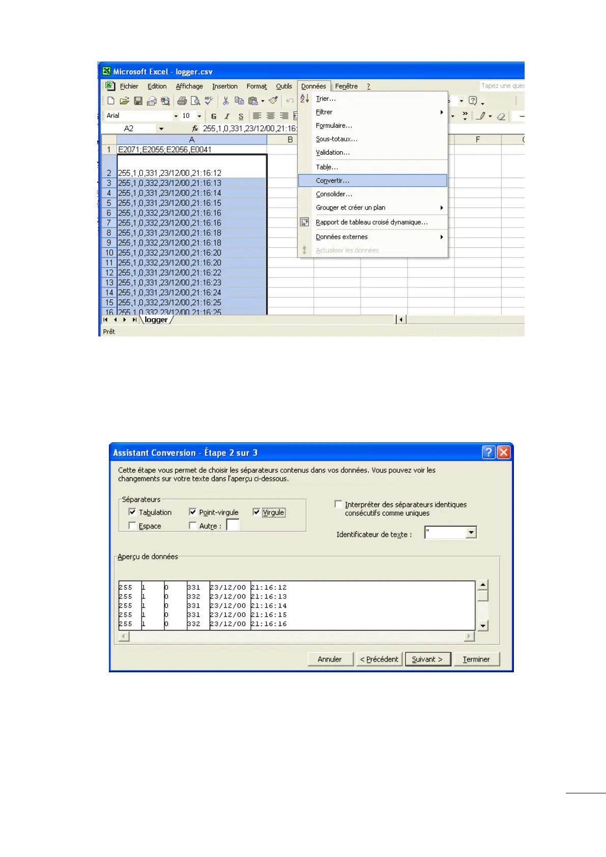
Click on "Data", then "convert".
Select "limited".
Select Table, Comma and Semicolon. Click "Next".
The variables, values, dates and times are now laid out in columns.

 Loading...