OPERATOR’S MANUAL
CMA-9000 FLIGHT MANAGEMENT SYSTEM
INKET
LEKKO
EHBK
THN
EHN
EHAM
183
HDG
LEKKO
1420.0z
18.1
NM
GS
TAS
210
240
179° /29
TRU
KLM00052
12
40
40
15
S
21
24
W
30
33
N
3
6
E
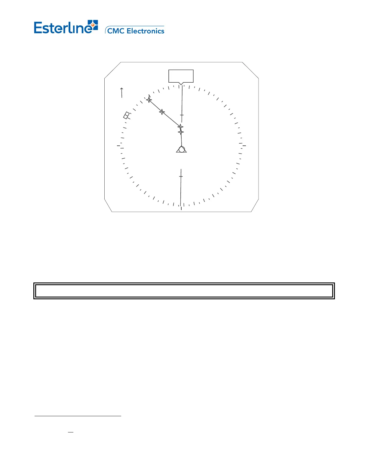
Typical CTR Mode
In both MAP and PLAN modes the Navigation Display shows dynamic data and symbols/vectors. The range of
the MAP and PLAN display modes can be set to 5
1
, 10, 20, 40, 80, 160, 320 or 640 nautical miles via the range
selector on the EFIS control panel.
NAVIGATION DISPLAYS -- SYMBOLOGY AND COLORS
The color conventions used on the Navigation Display are installation dependant, but are typically as follows:
Green (G) position data
White (W) armed flight modes, present status situation
Magenta (M) fly-to condition, engaged flight modes
Cyan (C) background information
Black (B) blank areas, ‘OFF’ condition
1
The 5 nm range is only available on certain installations. On such installations, the range may span from either
5 to 640 nm or
from 5 to 320 nm.
Page C-4
August 17, 2010